Laser imaging, detection, and ranging (LIDAR), is a method for measuring the distance to a targeted object in space. This works by aiming a laser at an object then firing pulses of light and receiving these using a light sensor next to the laser. The time it takes to receive the reflected light pulses can then be utilized to determine the distance of the object.
This project will utilize a laser that can be optically steered to aim in any direction. By scanning the lasers in every direction, a 3-dimensional image can be generated that gives a complete view of all surrounding obstacles. The ideal application for such a system is within self-driving cars, to detect other vehicles and pedestrians. This is also useful for 3d mapping either on land or underwater.
The Cloud Connectivity kit is ideal for this application as it includes an FPGA that is able to rapidly process the laser measurements in real-time which is essential for an application such as autonomous vehicles. The Wi-Fi connectivity combined with the Azure IoT application makes the platform even more powerful by allowing for results to be stored and processed further and then visualized to derive useful insights.
Demo Video
Project Proposal
1. High-level project introduction and performance expectation
Laser imaging, detection, and ranging (LIDAR), is a method for measuring the distance to a targeted object in space. This works by aiming a laser at an object then firing pulses of light, which are then received with a light sensor. The time it takes to receive the reflected light pulses can then be utilized to determine the distance of the object. This project aims to implement a basic LIDAR system powered by the DE-10 nano development board.
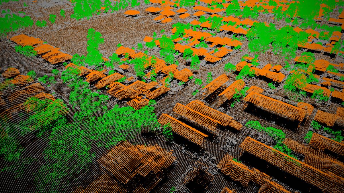
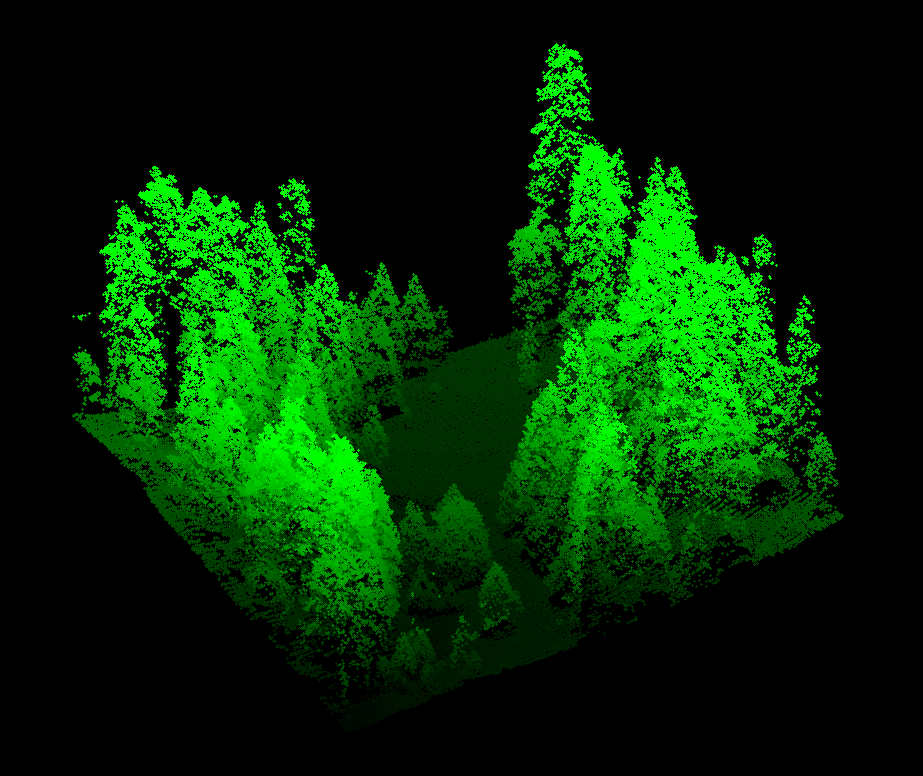
A 3D model of a forest generated via LIDAR
LIDAR is a powerful technology with an array of applications across multiple industries mainly utilized for 3D mapping. Mapping plays a role in enabling a sustainable future as it can assist scientists, conservationists, and engineers to understand how an area's geology, biodiversity, and terrain changes over time. Currently, LIDAR is being employed to study forests, glaciers, coastlines, and cities in incredible detail which cannot be achieved with any other current technology. Furthermore, LIDAR has been critical for developing autonomous vehicles which could pave the way to the development of smart cities where transport can be completely automated making it safer and more efficient.
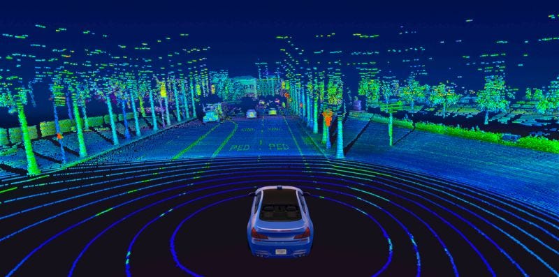
Example of LIDAR being used in a self-driving car
Intel FPGA devices are used in the design as they provide the ideal platform for processing the high volume of data from the laser sensor in real-time. The FPGA fabric enables the application to exploit parallelism which in this case, could involve processing data from multiple sensors concurrently as well as transmitting this data to the cloud or a local storage medium. Furthermore, the large number of I/O ports combined with the integrated microprocessor, enables the device to be incredibly modular to integrate seamlessly with current systems.
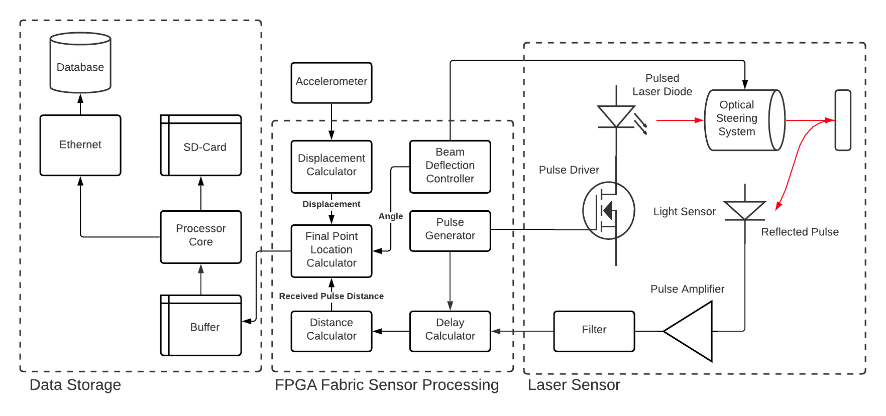
2. Block Diagram
3. Expected sustainability results, projected resource savings
Lidar enables diverse environments to be mapped helping us better understand how they change over time and what causes this to happen. It speeds up ways of monitoring the environment that can normally take a lot of time and resources. Lidar is completely non-invasive and low-powered meaning it does not negatively impact the environment being monitored.
Benefits of Intel FPGA:
Powerful Processing
To produce a high-resolution image, a high number of points per second should be measured. Commercial LIDAR systems from companies such as LIVOX claim to achieve rates of greater than 100,000 points per second. Achieving this speed requires that the FPGA process the sensor data extremely rapidly as well as being able to store or transmit the data at a comparable rate. The Intel FPGA fabric is capable of running up to 400Mhz which would leave 4000 clock cycles per point which should be more than enough to do all necessary processing. The processing could also be accelerated through pipelining the operations to achieve greater throughput if required.
Expansive I/O
To effectively utilize the LIDAR data, it is required that the FPGA can interface with storage devices, sensors, and user input devices. The Intel FPGA includes interfaces such as ethernet and SPI which give the flexibility to either send data to record on a computer or store the data directly onto an SD-CARD. The FPGA also includes A/D converters and an i2c bus which makes it simple to integrate with sensors such as accelerometers and GPS which are necessary when applying lidar imaging while in motion.
Fast High Capacity Memory
LIDAR scanners generate a huge amount of data that needs to be stored and retrieved from random access memory at a high rate. Intel FPGAs have the capability to interface with high-speed DDR3 memory to enable high data processing throughput enabling the LIDAR system to have higher resolution and lower latency.
Low Power
Many applications of LIDAR require the scanner system to be mounted onto vehicles such as drones which have limited battery life. Given that the Intel FPGA requires a low amount of power, it means that the LIDAR device can be made to be more efficient hence further extending its capabilities.
4. Design Introduction
My design is a LIDAR system implemented using an FPGA. The core part of the design is a pulsed laser diode producing light that is reflected by targeted obstacles and received utilizing a photodiode. The received pulses are then amplified and fed into the FPGA where the time difference between sending and receiving the pulses is calculated giving the distance the light traveled.
The purpose of this design is to create a cheap LIDAR solution by exploiting the processing power of an Intel FPGA. The Intel FPGA is an ideal solution as it also includes a high-speed hard processor core that works in conjunction with the FPGA fabric to enable advanced connectivity options making it easy to integrate into multiple applications.
The system is targeted to users who require a scanning LIDAR system but don't want to spend thousands of dollars. One intended application is for object detection in self-driving vehicles to make transport safer and more efficient. As well it could be utilized for performing aerial surveys to generate topological maps to monitor diverse environments making it an ideal tool for sustainability research.
5. Functional description and implementation
My design involves a custom PCB that plugs into one of the pin headers on the DE-10 nano. The purpose of this PCB is to connect an Infrared Emitter Diode to the FPGA which will drive it with a square wave at a set frequency. The PCB also includes a photodiode for receiving the reflected pulses and converting them into 3.3v digital logic via a trans-impedance amplifier and a comparator.
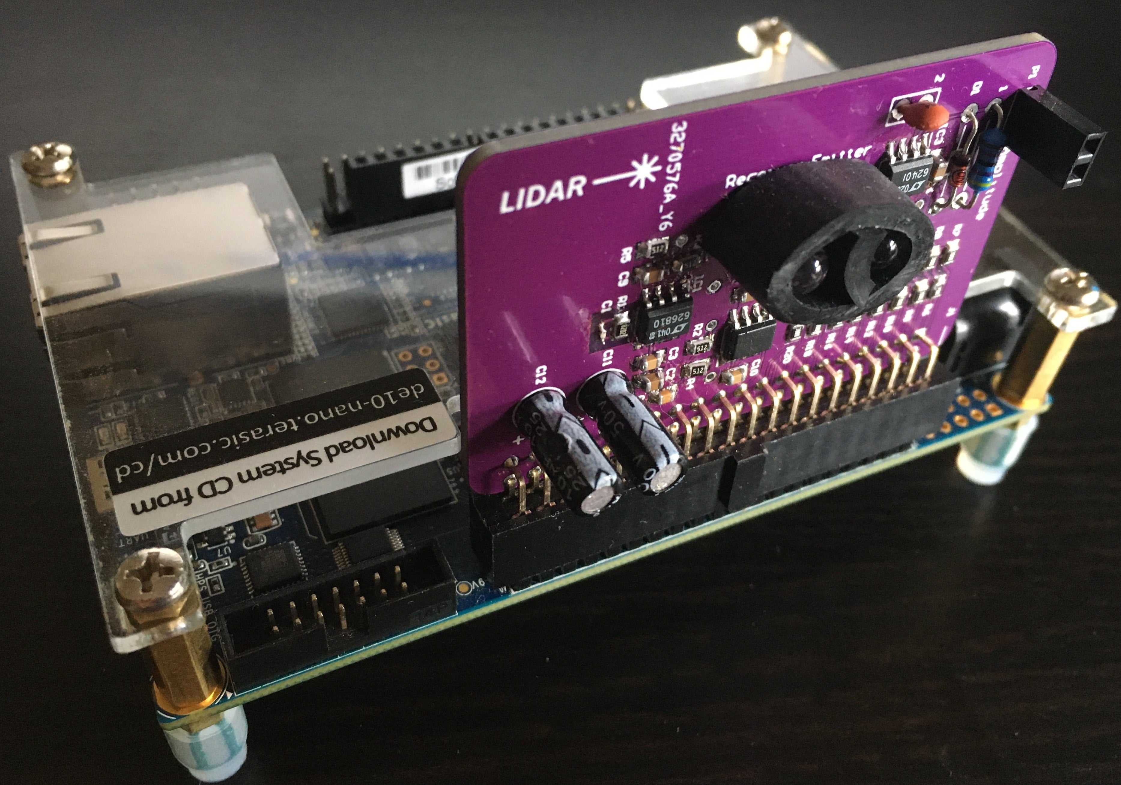
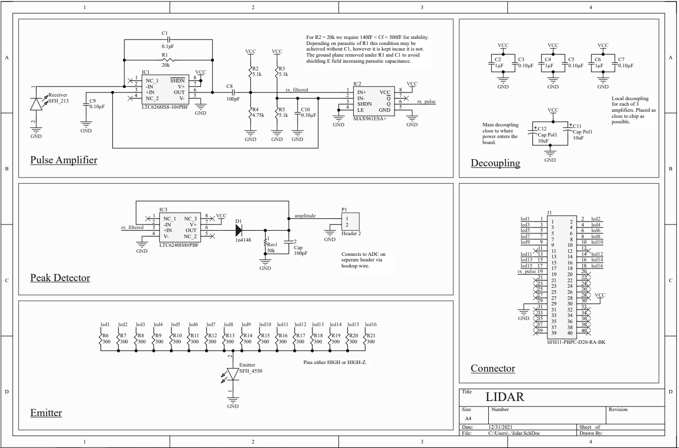
The schematic of the design shown below shows how all the individual components were connected. To amplify the received laser pulses received by an OSRAM™ SFH 213 photodiode, a high-speed transimpedance amplifier was built using the Analog Devices™ LTC6268 chip. This chip is an operational amplifier with a 4GHz gain-bandwidth product. Special attention to the power supply filtering and feedback path was necessary to ensure that there was no oscillation at the output. After amplifying the received pulses, the signal was fed into a high pass filter and then through the Maxim Integrated ™ MAX961 comparator which produced a 3.3v digital output with 5ns rise times.
To produce the laser pulses, the OSRAM™ SFH 4450 infrared emitter was connected to the FPGA via the current limiting resistor network. Multiple FPGA pins had to be used as the peak current for the laser diode was 100ma however a single pin could only supply 16ma maximum.
6. Performance metrics, performance to expectation
10,000 Points Per Second: 10,000 points per second appears to be a reasonable goal for the system as it would provide a resolution of 100x100 over the field of view which should produce data that is of high enough detail to be utilized.
30m Range: The range effectively depends on the power of the lasers utilized. For my project, I do not want to utilize a laser of very high power as it could become quite dangerous. I believe that 30m would be a suitable compromise that still enables the device to be useful.
40cm Precision: The precision of the device is limited by the clocking speed of the FPGA. Given that it can be clocked at around 400Mhz, the minimum time difference that can be detected is 2.5 nanoseconds. In 2.5 nanoseconds light can travel 75cm, however, the total traveled distance is actually twice the required distance so it should be able to have an accuracy of 37.5 cm. However it may be possible to improve upon this by interleaving the multiple onboard plls configured to different phases to improve upon this number. Experimentation with the board will be required to determine whether this is possible.
7. Sustainability results, resource savings achieved
The circuit did function as intended but unfortunately, the infrared emitter and photodiode combination was not suitable for the intended application. This meant that the pulses could only be received from a very short distance away. Given that the range precision would have been around 30cm, it was impossible to test ranging due to the fact that the pulses were only received over a distance of around 10cm. If I had more time and a greater budget I would have looked into using lasers specifically built for this purpose as well as highly sensitive avalanche photodiodes.
Not including the DE-10 nano development board, the project cost me $50 dollars in parts and a PCB. Commercial LIDAR systems can cost thousands of dollars, so if this design could be refined to work properly, it could definitely be a low-cost alternative to current solutions.
8. Conclusion
In conclusion, my project showed that it could be possible to build a low-cost LIDAR solution using the DE-10 nano FPGA development board. However, it was learned that more sensitive light sensors and a more powerful laser diode would be required to get this device working well which I may experiment more with in the future.
1 Comments
Please login to post a comment.
Enes Kağan LEVENTOĞLU
Good work, your project is great. Can you help with hardware?