Modern world having the issue to controlling the traffic at major cities for rapid increase in automobiles and also large time delays between traffic lights. So, in order to rectify this problem, we will go for different modes of traffic light control system. In this article, we have three modes i.e., Normal mode, Density mode, Emergency mode, IOT Mode.
Project Proposal
1. High-level project introduction and performance expectation
Modern world having the issue to controlling the traffic at major cities for rapid increase in automobiles and also large time delays between traffic lights. So, in order to rectify this problem, we will go for different modes of traffic light control system. In this article, we have three modes i.e., Normal mode, Density mode, Emergency mode. By interfacing these modes with FPGA using HDL language the switching of modes is performed.Modern world having the issue to controlling the traffic at major cities for rapid increase in automobiles and also large time delays between traffic lights. So, in order to rectify this problem, we will go for different modes of traffic light control system. In this article, we have three modes i.e., Normal mode, Density mode, Emergency mode. By interfacing these modes with FPGA using HDL language the switching of modes is performed.
Intel FPGA play the major role for development and support the updates if when ever need so we used Intel FPGA for our project.
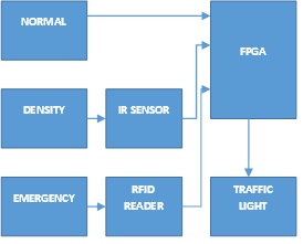
2. Block Diagram
3. Expected sustainability results, projected resource savings
The traffic light issue is a critical problem in day to day life of people and government. This can be rectified with the switching of traffic control based on the situations. The most commonly required in routine life are summed in three different modes of action.
- Normal mode
- Density mode
- Emergency mode
-
- NORMAL MODE:
At a specific period of time, only the green light holds ON and therefore the other lights remains OFF and after a while a changeover traffic signal control from green light to red light takes place by making the succeeding change for glowing of yellow LED. This process continues as a cycle and the timing for changing the LEDs can be displayed with the use of a seven segment display. This mode will be suitable for non- peak hours as there will be moderate or low count of vehicles.
3.2 DENSITY MODE:
This system consists of a FPGA 16F877A which does all the function according to code. Power supply is given to the microcontroller and the IR sensor on both the side of the road senses the density of the traffic and gives the information to the FPGA [3]. The controller provides output signal to traffic light.
|
POWER SUPPLY |
|
IR SENSOR |
|
FPGA |
|
TRAFFIC LIGHT |
 |
.
Fig 3.2.1: Block diagram of Density Mode
IR sensors are mounted on either side of each road. The distance between each IR sensors depend on the nature of the road. These IR transceivers are used to detect the vehicles passed through it. The IR transmitter generates a 38kHz square wave signal while the IR receiver connected to the traffic master controller receives the signal [4,7]. When a vehicle passes the road between the IR transceivers, the IR radiation spreads and the object is detected and the vehicle count is incremented. Then it will be given as input to the microcontroller, it can change the time delay of signals corresponding to the density value.
The IR transmitter looks like an LED. The white LED indicates IR transmitter and black indicates receiver. This IR transmitter emits IR rays from it. The operating voltage of the IR transmitter is basically 2- 3V. These IR rays are invisible to the human eye, but we can view these IR rays through camera. IR receiver accepts the IR rays that are transmitted by IR transmitter [3,4,7]. When it’s receiving IR rays the resistance is very low. The operating voltage of IR receiver is also 2- 3V. We have to place these IR pair on either sides of each row. IR receiver should be able to receive the IR rays when we give the power, the transmitted IR rays hit the object and reflected back to IR receiver.
3.3. EMERGENCY MODE:
Traffic Congestion is a root cause of various problems including traffic jams, traffic rules violations and accidents. This has adverse effect on human lives. The rescue vehicles are also facing such crisis due to these congestions that had already occurred on a road as there is no alternate in the existing TLC.
|
POWER SUPPLY |
|
RFID READER |
|
FPGA |
|
TRAFFIC LIGHT |
 |
Fig 3.3.1: Block diagram of Emergency Mode
This mode rectifies these issues with the help of Radio Frequency Identification (RFID). RFID is a wireless technology that uses radio frequency electromagnetic energy to carry information between RFID tag and RFID reader.
Some RFID systems will only work within the range inches or centimeters, while others may work for 100m (300 feet) or more [1,6]. Various types of tags are available but we can mainly divide them into 2 categories: Passive tags and Active tags. The passive tags don’t contain any internal power source. The active tags contain a battery as an inbuilt power source that wanted to operate microchips circuitry and to broadcast the knowledge to the reader.
FPGA is used here to control all the process that is involved. Here, the rescue vehicles and authorized vehicles are equipped with RFID tag which is placed at a specific location which cannot be removed easily.
This method makes use of RFID reader and FPGA to read the tag attached to the vehicle [8]. If the RFID- tag- read belong to those vehicles that are approaching a road junction, it’ll communicate to the traffic controller within the junction to show ON the GREEN light until the vehicle passes and red light for the other should be turned RED.
-
- LCD display
Liquid Crystal Display (LCD): 16x2 LCD used in the implemented to display data over 2 lines, each of 16 characters. Actually, two types of registers are used to configure the LCD; the command registers and control registers. Other aspects are LCD initialization, clearing the screen, setting the cursor position, and controlling display. While the data register holds the ASCII code of the characters that are appeared on the display.
-
- IR sensors AND LEDs
An infrared sensor is an electronic device used to detect the objects. It is used for measuring an object heat or its motion. The IR sensor emits or receives the infrared radiations that are invisible for the human eye. The working is simple: When IR radiation of the LED reaches the photodiode, the output voltages change according to the magnitude of the IR light (5 V or 0 V) [2,3].
It is universal that the black colour absorbs the entire radiation incident on it and white colour reflects the entire radiation incident on it. It consists of an IR LED, a photodiode, a potentiometer, an IC Op-Amp and an LED emits infrared light. The Traffic lights contains three universal coloured lights: the green light allows traffic to proceed within the indicated directions, the traffic yellow light warns vehicles to organize for brief stop and therefore the red signal prohibits any traffic from proceeding.
-
- RFID Tags
Radio Frequency Identification System uses electromagnetic fields for automatic identification. It is a modern technology that is actually based identification system which helps identifying objects just through the tags attached to them, without requiring any light of vision between those tags and the tag reader which is placed. All that’s needed is radio communication between the tag and therefore the reader.
A RFID Tag comprises of a silicon microchip which is attached to a small sized antenna and placed on a substrate and encapsulated in several materials like plastic or glass veil and with an adhesive on the rear side to be attached to objects or vehicles [6,8].
A reader consists of a scanner with antennas to transmit and receive signals and is responsible for communication with the tag and receives the information from the tag. A Processor or a Controller can be a host computer within which a Microprocessor or a Microcontroller receives the reader input and process the data.
0 Comments
Please login to post a comment.