With time the rate at which we are producing data is increasing at a very tremendous rate. And it seems that this trend will continue with our advancements in technologies and user requirements. One of the big portions of the world’s overall data transmission and data storage is our Videos and Images. Security and surveillance, entertainment, streaming, and roughly every other industry use this kind of data for their applications and the demand for data is increasing than ever. But this increasing demand for data causes two major (global) issues: first, during transmission, they can take a lot of bandwidth of our network, and second that they tend to take a lot of storage space since we need a lot of data points to effectively utilize them for our needs.
Here, this project will be showing the downscaling and upscaling algorithms that are already used in many applications for quite a few years and implementing these algorithms on FPGA and cloud effectively to get the best possible results. Initially, data can be taken from a low-resolution input(or can be downscaled) and then transmitted/stored. When we have to use it, upscaling can be done. These algorithms show very promising results while using fewer resources as to if directly high-resolution input be used from the beginning.
This will give us more bandwidth and storage to work with for our applications, and as computation will be done on FPGA, it will be easily scalable. Edge computing like this will effectively increase productivity and will help in a sustainable advancement in technology. For the continuous advancement in technology and sustainable growth, we have to use our resources efficiently and intelligently and I hope that this project can play a small part in this.
Project Proposal
1. High-level project introduction and performance expectation
Purpose of the design
With improvement in camera technologies, screen technologies and computer graphics, image quality is getting better and better. This also means that the size of the image is also increasing as we are saving more information. But still, a large amount of data that we produce is still in low-resolution (LR) as compared to these new technologies. There are many reasons that we produce LR data. Firstly, a lot of devices in the market support them and thus when we create a product, we may produce LR data to support those devices. Second, depending on the use case (Security cameras etc.), where we continuously produce data and we have limited storage, we produce LR data. Finally, to use less resources, save power we sometimes also go for low-resolution devices. That means if we want to view that data, we need to somehow upscale that low resolution data to high resolution (HR). There are many methods for doing that, it can be either done by algorithms of interpolation like nearest neighbor interpolation, bilinear interpolation or bicubic interpolation. There are other methods that are based on Machine Learning(ML) models for upscaling or super-resolution. ML methods give best results in case of upscaling of images but on embedded devices like Television, Monitor, these ML models are not feasible as we don’t have enough available resources for using these models. In these cases, FPGA can be used efficiently to do the image processing. These can also be used to convert HR data to LR data before saving the data to reduce memory use and to save network bandwidth if transferring the data.
Application Scope
Application wise this project can have a variety of uses. For data centers where this kind of data is stored, this method could effectively increase capacity as we will be using fewer resources for the same(similar) data. For applications where constant data is streamed(eg. Video conferences, IoT, etc.), this can help to reduce the load on the network. It can also take some load of the existing hardware by reducing the complexity it has to work with. It can also be used in image restoration or in details enhancers where these algorithms are vital to get accurate results.
Why Use Intel FPGA Devices
Intel-FPGA inside de10-nano has many capabilities and elements that make it a good choice for the project.
-
Logic elements(LE): This intel-FPGA comes with 110K LE which will make it possible to create even some complex designs. These are important for our project as they can be used to create our design in the FPGA that will be specific to our algorithm and thus the FPGA parallelism and custom design will help us to create a fast and efficient logic.
-
DSP blocks and Multipliers: 112 DSP blocks and 224 18x19 multipliers are built inside this FPGA. As our project consists of upscaling and downscaling the input data, these blocks are vital for our project.
-
Embedded memory: 5570 Kb of memory is already present inside the FPGA which is required for storing the intermediate data and will also help in the implementation of the algorithm.
-
User I/Os: This FPGA has a lot of user I/Os, 145 to be exact. It will help us to easily connect it with other modules(eg. WiFi).
-
Hard processor system(HPS): Intel-FPGA is a system on a chip(SoC) and also has an HPS block inside it. That contains Dual-core ARM cortex-A9, 64 KB on-chip memory, DDR3 controller, and many other functionalities. These all make it easy to integrate the design with other components and the outside world.
-
Support: Finally, this FPGA has support for a lot of resources like Linux which plays a vital role in algorithm development. This all adds up to make this a solid choice for the project.
Of course, there are many other functions of the FPGA chip and the board itself that will play an important role in the design but it would not be ideal to list everything here. Here only those components are defined that are extremely relevant for the project. For the rest of the specifications and functionalities, one can refer to Intel's website.
One of the main points is that the hardware of an FPGA is programmable and because of massive parallelism, we can compute more data at the same time thus increasing speed.
2. Block Diagram

Fig. 1: Data flow of the system
3. Expected sustainability results, projected resource savings
The performance of the system depends on a few key parameters:
-
System can Upscale/Downscale the image.
-
Data can be provided to the system through external devices.
-
All the calculations are done on the DE10 nano board.
-
Data can be sent from the system to the external devices.
-
System uses the interpolation technique to change the resolution of the input image.
The target is to create a system that can Upscale or downscale images fast enough that it can be used as an extension to everyday systems. Because the system will be dedicated to do this work, it can be used to take the load off the system it is attached to. It will also be able to reduce the size of the data so it can be used to save memory and thus reduce storage needed to save the data.
4. Design Introduction
The system hardware only consists of De10 nano board, RFS board and ethernet connection. The De10 nano board has two ARM processors which are running the linux system and acts as master to the FPGA board. The De10 nano board takes the image data and saves it in its memory on the HPS side. The image can be transferred to the system from any external device from the connections provided(example ethernet). The linux system takes the image, converts it to matrix and then selects part of it while looping over the entire matrix. The chosen data is sent to the next part along with the command to either upscale or downscale it. Necessary calculations are done on the data and then it is sent back to the loop.
This process is repeated on the whole matrix after which, we convert the data back into the image. The final image is sent back to the device from which it came from or can be sent or saved anywhere else if required.
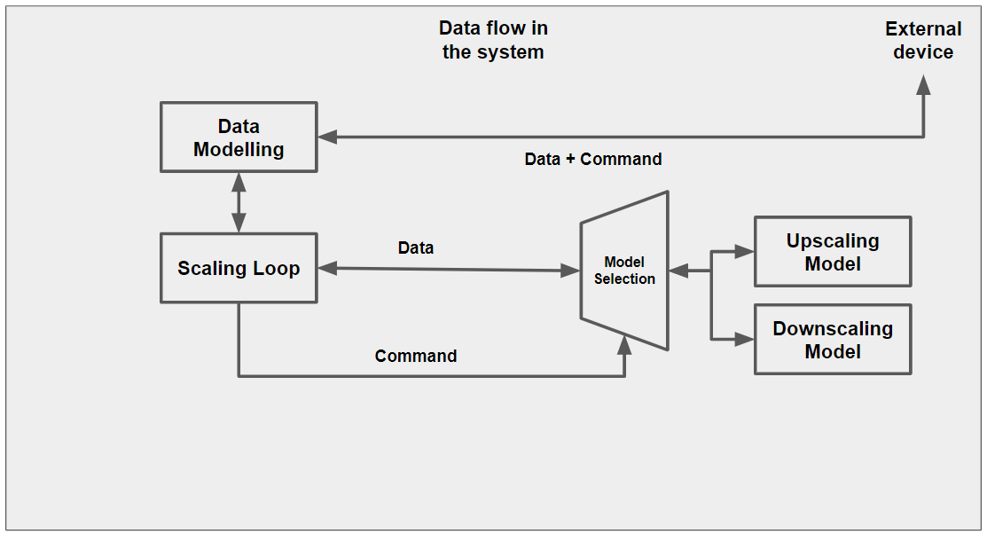
Fig. 2: Basic model of system
5. Functional description and implementation
The most important part of the system is interpolation. Interpolation basically means to insert external data in our existing dataset. If we have some image dataset, we can use that to find the pattern or correlation between each set of pixels. That can be used to find pixels in between a set of few pixels, it is known as upscaling. Similarly, that can be used to replace a set of pixels by a smaller number of pixels, it is called downscaling. There are three interpolation methods that are used extensively in image upscaling/downscaling: nearest neighbor interpolation, bilinear interpolation or bicubic interpolation. Below these techniques are described for the case of upscaling as it will be easier to understand them this way. To describe the methods, we take a set of 2x2 dataset and upscale it to a 4x4 dataset.
In the case of nearest neighbor interpolation, we simply copy the given input data to output data according to the ratio of upscaling. As can be seen in figure 3, we convert a 2x2 matrix to 4x4 matrix by simply copying the data two times.
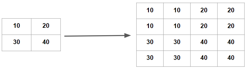
Fig. 3: Nearest neighbor interpolation for 2x2 matrix
In the second method of interpolation i.e. bilinear interpolation, we use a linear equation in both directions (x and y) to get a point in between four given points. This way, we take the weighted mean of those points to find the desired point as can be seen in figure 4.
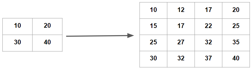
Fig. 5: Bilinear interpolation for 2x2 matrix
Finally we come to the bicubic interpolation method. Here, we take a cubic equation in both directions (x and y) to find the desired point. In this case, we take sixteen data points to find the desired point. It can be seen clearly in figure 5. As we only have four data points in the example, we first increase the data points by using the first two methods and then use bicubic to find the desired data points.
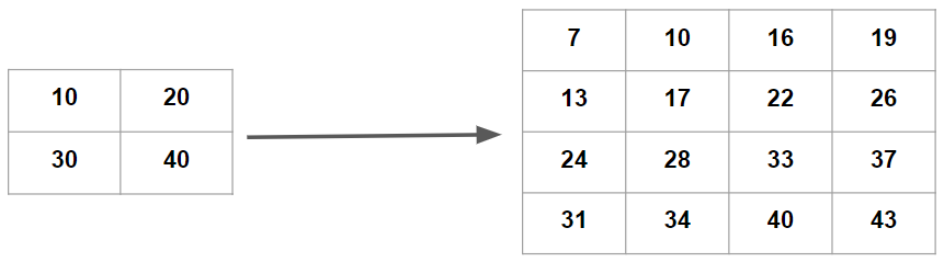
Fig. 5: Bicubic interpolation for 2x2 matrix
Bicubic method is the most difficult and most complex in these three methods but also gives the best result. As seen in figure 6, we take a part of the input image for comparison and compare the results as given by these three methods as shown in figure 7. Here in our system, we have applied bicubic interpolation methods for upscaling and bilinear interpolation for downscaling. The reason for that is the fact that upscaling biliner shows most promising results but for downscaling we can simply work with taking the weighted mean of the image pixels. Both scaling works as a 2x ratio i.e., we always upscales or downscales the input data two times.

Fig. 6: Input Image (Part shown that is used for comparison)
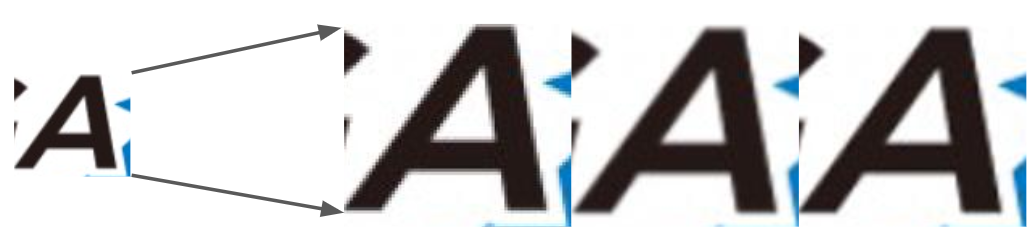
Fig. 7: a) Input image, b) Image from nearest neighbor,
c) Image from bilinear, d) Image from bicubic
6. Performance metrics, performance to expectation
Below are a few points that describes the benefits and metrics of the system:
-
The system just requires DE10 nano for computation. Thus, the system is comparatively cheap.
-
The system can be easily integrated to any existing system that we use daily like, it can be connected to a router, can be used in data centers. The system will only work when we have to upscale/downscale the image.
-
System can be used in TVs, set-up boxes, monitors to upscale the input image to the screen's native resolution. It will take the load of the main processor that can be used for other processes.
-
System consumes far less power as compared to CPUs and GPUs that are usually used for this kind of processes.
-
Processing speed is good and results are desirable.
7. Sustainability results, resource savings achieved
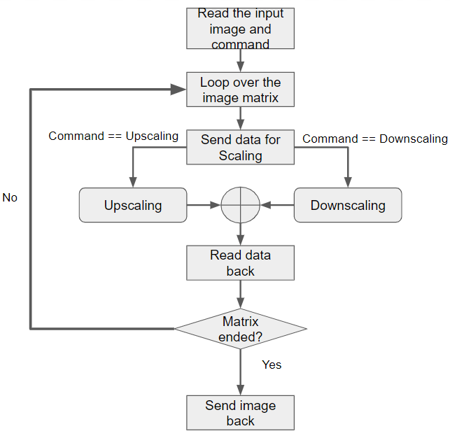
Fig. 8: Software flow of the system
8. Conclusion
In this project, we have shown a system that can be used to upscale or downscale an input image. The system consists of the cloud connectivity kit (De10 nano + RFS board) where De10 nano board is the master in the system as all the work is done by it. We have used the interpolation algorithms for the scaling of images.
For further work, attach the system to the cloud to control it from there and for other necessary data transmissions. We can also make a few changes to support video data for scaling. Other than that, other algorithms that depend on ML can be implemented on the system and then a comparison can be done to see the difference from the current method. Here in this project we have shown that this kind of work is possible on the platform that was provided and further improvements are possible to make it more useful in the future.
0 Comments
Please login to post a comment.