The proposed system is a system which will closely monitor the parameters of a field on a regular basis round the clock for cultivation of crops or specific plant species which could maximize their production over the whole crop growth season and to eliminate the difficulties involved in the system by reducing human intervention to the best possible extent.
We mainly have Two Blocks for this Project:
a. HPS (Hard Processor System):
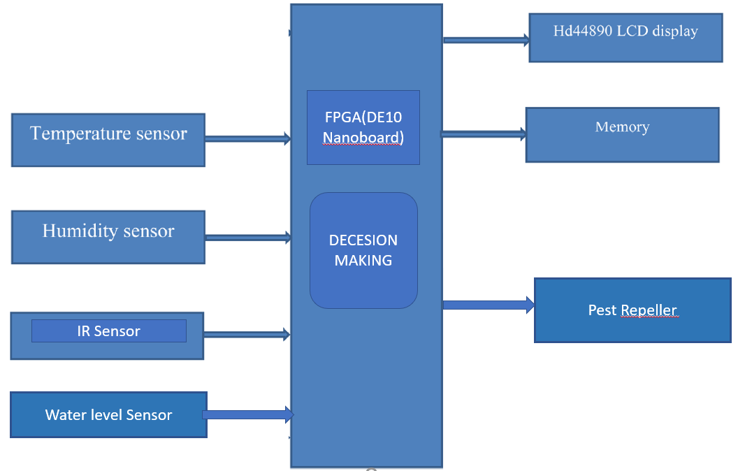
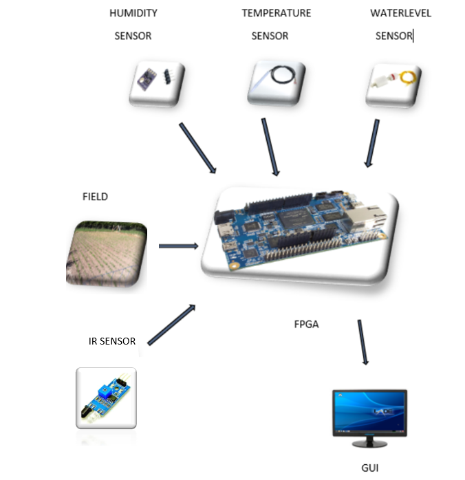
Our system will take multi-inputs from multiple sensors such as humidity, light intensity, temperature and IR sensor and give those parameters as input to the HPS automatic training module (as initial values). For certain time the process of taking multiple input will be repeated over time. These will be an input to the HPS. Post processing the data will give as input to the FPGA part.
b. FPGA (Field Programmable Gate Array (Terasic DE10-Nano FPGA)):
By taking the input data in HPS as input to the FPGA part of the board, the system will pre-process the data. Then, it compares both the data and make the result. The result will be sent to the display as a message
Our main aim of the Digital Farming is to improve agricultural yield and reduce potential environmental risks, while benefits are:
1. Water level sensing.
2. Atmospheric temperature sensing.
3. Atmospheric humidity sensing.
4. Detection of pest in the field and automatically start the pest repeller if pest is detected using IR sensor.
5. Suggest best measures to be taken by the farmer.
1. Water Level Sensing:
An advanced water level sensing sensor will be fixed in the field for monitoring the water level. Based on the information given to the system, our system will alert the farmer along with the water level percentage through message.
2. Atmospheric Temperature sensing:
A temperature sensing device will be fixed at the field for checking the temperature of the present atmosphere. Our employed FPGA will decide whether the atmospheric temperature is sufficient for field growth or not and send the information through message.
3. Atmospheric Humidity sensing:
An atmospheric humidity sensing sensor will be placed at the field for checking the humidity present in the atmosphere. The output of the sensor will be given as input to FPGA for checking humidity is high or normal for crops growing. Our system will send this Atmospheric humidity level to the farmer through message.
4. Detection of pests such as rodents:
Here using IR sensors detects the entry and exit of unwanted pests such as rodents.
5. Diagnosis and Suggest some measure to be taken by farmer:
After detecting the sensor inputs from the field, our system will send the actions to be taken and suggest some precautionary measures.
This project is divided into four phases: -
Identifying the appropriate sensor for measuring temperature and relative humidity. Temperature sensor to be used is RTD so that low-cost aim can be successful with best stability.
Design of controller using FPGA, sensor interface card, isolation circuit for input and output, output relay card.
Identify if there any pests enter into the premisses/field and take the necessary action if so.
Development of a user interface and the controlling software.
Since a FPGA(Terasic DE10-Nano FPGA) is used as the heart of the system, it makes the set-up low-cost and effective nevertheless. As the system also employs an LCD display for continuously alerting the user about the condition inside the greenhouse, the entire set-up becomes user friendly.
Project Proposal
1. High-level project introduction and performance expectation
Linking skill with agriculture is one of the significant areas that is to be taken at most significant. Agriculture is a fine art of raising plant life from the soil for the use of mankind. Agriculture is the mile stone in the history of human civilization, due to agriculture man settled at particular place. About 70% of the Indian population practices agriculture. Hence, the production and management of crops is an important aspect to ensure optimal productivity in the fields. The major agricultural practices involved in crop production and management are preparation of soil, sowing of seeds, addition of manure and fertilizers, Irrigation, protection from pests, harvesting storage. Agriculture is the main backbone of Indian economy.
Farming is the back bone of Indian economy. Agriculture in India has a significant history. The cultivation of crops is much needed for the survive of human kind. India is well known for its agricultural work. It plays a crucial role for providing employment to most of the people. The development of agriculture is considered to be necessary for the advancement of the countries from traditional to modern economy. Almost all the farmers are still depending on the traditional way of cultivation. We are observing that the yield of crops and fruits are not at all being increasing. The farmer is facing a lot of difficulties while cultivating the crops.
But the crops are facing possible problems namely pests, water scarcity and thereby triggering huge loss for the farmers. That’s why farmers are nursing the crops day-to-day.
It is observed that, in most of the cases farmers will identify the issue at hand by identification and will take the proper action to overcome those complications. For the farmers, those who are mindful of these problems will easily handle the situation but in the case of farmers, who don’t have appropriate knowledge about of it, will take inappropriate actions. This will destroy the entire crop and cause a huge loss to farmer.
These results into giant waste of human work, loss of time and money.
The primary solution for these problems is ‘Digital Farming’.
Digital Farming is applying meticulousness location methods and decision superiority agronomical information to brighten, predict and affect the continuum of cultivation issues across the farm. By using these techniques our system will work as a guide, to assist the farmers by giving information about Water level, Atmospheric humidity, Temperature and about plant growth, plants affected by pests in the field for the entire life span of the crop. Instantaneously it will suggest instant actions to be taken to overcome those complications and will suggest the best practises to the farmer.
This complete setup of processing will be performed on FPGA DE Nano-10 board to use the features of parallelism and pipelining architecture for getting high speed and accuracy in assessment.
Field programmable gate array (FPGA) has revolutionized
the prototyping and verification of the conceptual design.
FPGA has taken over the silicon VLSI in a number of factors
which includes the speed of the system, no of input/output
ports and overall performance of the system.
Field programmable gate array (FPGA) has revolutionized
the prototyping and verification of the conceptual design.
FPGA has taken over the silicon VLSI in a number of factors
which includes the speed of the system, no of input/output
ports and overall performance of the system.
Field programmable gate array (FPGA) has revolutionized
the prototyping and verification of the conceptual design.
FPGA has taken over the silicon VLSI in a number of factors
which includes the speed of the system, no of input/output
ports and overall performance of the system.
Field programmable gate array (FPGA) has revolutionized
the prototyping and verification of the conceptual design.
FPGA has taken over the silicon VLSI in a number of factors
which includes the speed of the system, no of input/output
ports and overall performance of the system.
Field programmable gate array (FPGA) has revolutionized
the prototyping and verification of the conceptual design.
FPGA has taken over the silicon VLSI in a number of factors
which includes the speed of the system, no of input/output
ports and overall performance of the system.
Field programmable gate array (FPGA) has revolutionized
the prototyping and verification of the conceptual design.
FPGA has taken over the silicon VLSI in a number of factors
which includes the speed of the system, no of input/output
ports and overall performance of the system.
The most important factors for the quality and productivity of plant growth are temperature, humidity, light and the water content present in the soil. Continuous monitoring of these environmental variables gives information to the grower to better understand, how each factor affects growth and how to manage maximal crop productiveness.
However, more measurement data is also needed to make this kind of automation system work properly. Increased number of measurement points should not dramatically increase the automation system cost. It should also be possible to easily change the location of the measurement points according to the particular needs, which depend on the specific plant, on the possible changes in the external weather and the plant placement in the fields.
For the implementation of agricultural technologies, low cost and real time remote monitoring are needed, in this sense, FPGA(Terasic DE10-Nano FPGA) present as a good option for the technology development and implementation, because FPGAs allow fast development of prototypes and the design of complex hardware systems/inputs.
Crop growth is mainly influenced by the surrounding environmental climatic variables and by the amount of water and fertilizers supplied by irrigation. Another major difficulty faced by the farmers is to protect the crops from pest that destroy the crops. The pest are organisms which can damage crops and compete with them. They tend to decrease the crop yield by being the reason in stunted growth of the plant, and spreading diseases. Pest control is the regulation or management of a species defined as a pest, a member of the animal kingdom that impacts adversely on human activities. This can be achieved by monitoring the crop, only applying insecticides when necessary, and by growing varieties and crops which are resistant to pests. These complications can be abolished by modern technology FPGA.
Nowadays, FPGA has a good development prospect in the image processing, and many image processing algorithms have been proposed based on FPGA architecture. Some researchers also developed embedded graphics processing unit (GPU) for precision weed management. But in field robot vision guidance, few literatures have been reported about FPGA (Field programmable gate array )
(FPGA(Terasic DE10-Nano FPGA)) has revolutionized the prototyping and verification of the conceptual design. FPGA has taken over the silicon VLSI in a number of factors which includes the speed of the system, no of input/output ports and overall performance of the system.
Aiming at the above problems like pest, in this paper we are going to propose the method to control pest with the help of FPGA. As the agricultural sector is facing many challenges regarding climate change, the current challenges of the less favourable climatic conditions flourish the more serious hazards for crops. The climatic conditions influence crop production which results in the economic loss to the farmers. Therefore, continuous monitoring of the climatic conditions is suggested to reduce the attack of pest on agricultural crops. Different environmental parameters such as temperature, humidity, rainfall, and wind speed could be monitored through FPGA technology. As a result, pest control would be held through the data of environmental parameters through FPGA. By using this model the farmer can control the pests and monitor the soil moisture, water level, and temperature, humidity, and dew point sensors for the better cultivation of the crop. For the implementation of agricultural technologies, low cost and real time remote monitoring are needed, in this sense, Field Programmable Gate Arrays present as a good option for the technology development and implementation, because FPGAs allow fast development of prototypes and its less complex when compared to other technology.
This paper consists of different sensors like temperature sensor, humidity sensor, IR sensor, pest repellent sensor, dew point sensor, soil moisture sensor water level sensor is interfaced with FPGA. The sensors will monitor the field conditions, and the sensors information will be stored in memory. Here the farmer will take the required information and he can take necessary precautions to his fields. The parameters for different devices were compared. By using HDL (Hardware Description Language) language the overall system architecture was designed. The simulation and synthesis are done using EDA tools.
This system will monitor all these parameters through different sensors. Soil moisture sensor will measure the water content in the soil i.e.; it will check whether the soil is dry or wet. Water level sensor senses the water in the water source. Temperature sensor and humidity sensor are used for forecasting the weather conditions. Dew point sensor will convert the water vapour into liquid state. When any of the climatic parameters like temperature, IR, pest repellent, humidity crosses a safety threshold which has to be maintained to protect the crops the sensor sense the change and the FPGA reads this data at its input ports after being converted to a digital form by the ADC. The FPGA then performs the needed actions. As the system also employs memory in which all the sensor values are stored.
Environmental parameters:
Water Sensing:
A reliable supply of good quality water is critical for any mixed farming enterprise. Prolonged dry seasons over the years have highlighted the value of this precious resource. Water is needed for stock, garden and domestic use, as well as for a variety of other purposes.
Knowing water requirements is needed to inform whole farm planning, drought preparation and upgrading of water infrastructure. The figures will vary significantly depending on:
- farm location
- type of stock
- management practices.
When calculating your water requirements it is important to consider:
- your future needs
- drought
- water quality
- available water resources.
Light Intensity
For proper growth of plants in greenhouse required light intensity should be around 50,000 to 60,000 LUX is needed. Light intensity in India is around 40,000 to 1, 40,000 LUX. Thus using shade nets we have to reduce this light intensity.
Temperature
Temperature for plant (flowers or vegetables) growth required is Day temperature around 26degreeC to 30degreeC Night temperature around 15degree C to 18degree C. This temperature can be controlled by watering the plants with the required amount of water.
Humidity
For floriculture 70% to 80% humidity should be maintained and for vegetables 60% to 70% humidity is required.
Pest Control:
Nearly 20% of the world’s food supply is consumed by rodents.
Rodents are prime carriers for dangerous pests such as fleas, ticks, and mites. This creature carries diseases that are transmittable to humans and animals. This is controller using IR detectors for detecting and pest repeller.
2. Block Diagram
3. Expected sustainability results, projected resource savings
Daily monitoring of agricultural field condition by humans in day-to-day life is not possible today’s world. In order to improve the efficiency of the data collection procedure, and to improve the precision with which agricultural operations are managed, it is necessary that we have an automated system that collects environmental data, especially to record long-term and up-to-the-minute environmental fluctuations. We also intend to target the pest menace and use automation as a tool to fend crops from pests.
The expected result is to help the farmers by improving their yield by 15%. We expect to achieve competitiveness in the market,
the production cost must be kept as low as possible. Low-cost automation can be achieved by using FPGA systems so that all category farmers can afford it.
4. Design Introduction
We mainly have Two Blocks for this Project:
a. HPS (Hard Processor System):
Our system will take multi-inputs from multiple sensors such as humidity, light intensity, temperature and IR sensor and give those parameters as input to the HPS automatic training module (as initial values). For certain time the process of taking multiple input will be repeated over time. These will be an input to the HPS. Post processing the data will give as input to the FPGA part.
b. FPGA (Field Programmable Gate Array (Terasic DE10-Nano FPGA)):
By taking the input data in HPS as input to the FPGA part of the board, the system will pre-process the data. Then, it compares both the data and make the result. The result will be sent to the display as a message
Our main aim of the Digital Farming is to improve agricultural yield and reduce potential environmental risks, while benefits are:
- Water level sensing.
- Atmospheric temperature sensing.
- Atmospheric humidity sensing.
- Detection of pest in the field and automatically start the pest repeller if pest is detected using IR sensor.
- Suggest best measures to be taken by the farmer.
5. Functional description and implementation
Sensors:
Temperature sensor
It is used to measure temperature readings through electrical signals. The sensor is made up of two metals, which generate electrical voltage or resistance once it notices a change in temperature. The temperature sensor plays a critical role in maintaining a specific temperature within any equipment used to make anything from medicine to beer. To produce these types of content, the accuracy and responsiveness of the temperature and temperature control are critical to ensuring the end product is perfect. Temperature is the most common physical measurement type in industrial applications. Accurate measurements are vital in ensuring the success of these processes. The two main types of temperature sensors are: Contact Type Temperature Sensors: There are a few temperature meters that measure the degree of hotness or coolness in an object by being in direct contact with it. Such temperature sensors fall under the category contact-type. They can be used to detect solids, liquids or gases over a wide range of temperatures. Non-Contact Type Temperature Sensors: These types of temperature meters are not in direct contact of the object rather, they measure the degree of hotness or coolness through the radiation emitted by the heat source. The technology employed in this specific non-contact sensor will very much depend on the parameter or condition being monitored (e.g. temperature, pressure, vibration, position, etc.)This paper gonna use Non- contact temperature sensors – RTD - or Resistance Temperature Detectors - are temperature sensors that contain a resistor that changes resistance value as its temperature changes. The pt100 is one of the most accurate temperature sensors. Not only does it provide good accuracy, it also provides excellent stability and repeatability. Most OMEGA standard pt100 comply with DIN-IEC Class B. Pt100 are also relatively immune to electrical noise and therefore well suited for temperature measurement in Agricultural applications.
|
Sensor Type |
Pt100 (100 Ohms @ 0°C) to IEC 751, Class B, 4 wire |
|
Process Connection |
Stainless steel plug (no thread) |
|
Probe Diameter |
6mm |
|
Probe Length |
Various |
|
Sheath Material |
316 stainless steel |
|
Head Type |
DIN B |
|
Max. Temperature |
+450°C (connection head @ 170°C) |
|
Min. Temperature |
-50°C |
|
IP Rating |
IP67 |
|
Accuracy |
Class B |
|
The sensor type, Pt100, indicates two important pieces of information about the sensor. The first part, Pt, is the chemical symbol for Platinum and this shows that the sensor is Platinum-based. The second part, 100, relates to the resistance of the device at 0°C. In this case 100Ω. There are a number of variations on this theme. |
There are other materials that can be used such as Nickel (Ni) and Copper (Cu) and different resistance values such as 50Ω, 500Ω and 1000Ω.
The above diagram shows the working principle of PT100 temperature sensor. This sensor helps us to measure the atmospheric temperature.
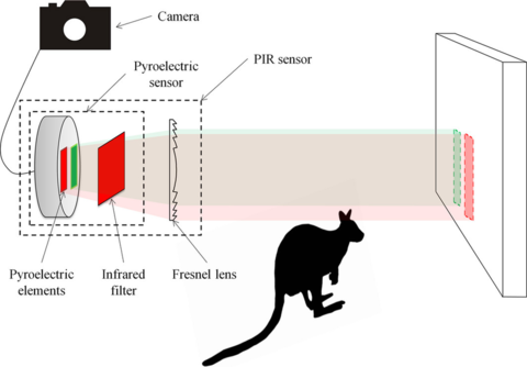
IR Sensor
An infrared (IR) sensor is an electronic device that measures and detects infrared radiation in its surrounding environment. Anything that emits heat (everything that has a temperature above around five degrees Kelvin) gives off infrared radiation. There are two types of infrared sensors: active and passive. Active infrared sensors both emit and detect infrared radiation. Active IR sensors have two parts: a light emitting diode (LED) and a receiver. When an object comes close to the sensor, the infrared light from the LED reflects off of the object and is detected by the receiver. Active IR sensors act as proximity sensors, and they are commonly used in obstacle detection systems (such as in robots).Thus the IR sensor is used for pest detection and so the its controlled by the repellent in our model.
Infrared Obstacle Avoidance IR Sensor Module (Active Low) has a pair of infrared transmitting and receiving tubes. When the transmitted light waves are reflected back, the reflected IR waves will be received by the receiver tube. The on board comparator circuitry does the processing and the green indicator LED comes to life. The module features a 3 wire interface with Vcc, GND and an OUTPUT pin on its tail. It works fine with 3.3 to 5V levels. Upon hindrance/reflectance, the output pin gives out a digital signal (a low-level signal). The on board preset helps to fine-tune the range of operation, the effective distance range is 2cm to 80cm.
|
|
Hence there is a line of sight communication between the infrared transmitter and the receiver. If an object falls in this line, it obstructs the radiation from reaching the receiver either by reflecting the radiation or absorbing the radiation. Thus the Pest is detected by the IR sensor.
Humidity sensor:
Humidity is defined as the amount of water present in the surrounding air. This water content in the air is a key factor in the wellness of mankind For example, we will feel comfortable even if the temperature is 00C with less humidity i.e. the air is dry. But if the temperature is 100C and the humidity is high i.e. the water content of air is high, then we will feel quite uncomfortable. Such sensitive equipment must be operated in a humidity environment that is suitable for the device. Hence, sensing, measuring, monitoring and controlling humidity is a very important task and the moisture in the soil plays an important role in the proper growth of the plant. So, it has to be maintained properly with the help of humidity sensor.
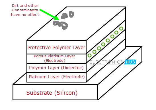
A simple Capacitive RH Sensor can be made from an air filled capacitor as the moisture in the atmosphere changes its permittivity. But for practical applications, air as a dielectric is not feasible. Hence, the space between the capacitor plates is usually filled with an appropriate dielectric material (isolator), whose dielectric constant varies when it is subjected to change in humidity. The common method of constructing a capacitive RH sensor is to use a hygroscopic polymer film as dielectric and depositing two layers of electrodes on the either side.
HR 202 Humidity Detection Sensor Module
- Adjustable Sensitivity, External GND.
- Detect Ambient Humidity.
- Provided with Fixed Bolt Hole, Convenient to Install.
- Power Indicator Light & Digital Output Indication Lamp.
- Using LM393 Chip for Stable Work.
- DO Small Digital Outputs Interface (0 & 1).
Using high-quality HR202 humidity sensor. The comparator output signal is clean, good waveform, driving ability, more than 15mA. The humidity sensor module is sensitive to environmental humidity, generally used to detect ambient humidity by adjusting the potentiometer, for detecting the humidity can change the threshold ( i.e. the humidity control), such as the need to control the ambient humidity of 60% ,then the corresponding module is transferred to the green light and humidity environment, DO high power output when flat, humidity values below this setting, high output, the green light does not shine. DO output can be directly connected to the microcontroller through the microcontroller to detect high and low, thereby detecting the humidity changes in the environment. DO output of the relay module can directly drive the shop, which can form a humidity switch, control-related equipment to work in the right environment. Small plates AO analog output modules can be connected OUR AD through the AD converter, you can get a more accurate numerical ambient humidity With the screw holes of 3mm, easy fixed installation. Thus the HR 202 humidity detection sensor module is used to monitors the moisture of the soil.
Light Intensity sensor:
A Light Sensor is a device that detects light. It generates an output signal that is proportional to the intensity of light. A light sensor measures the radiant energy present in the wide range of frequencies in the light spectrum. Some of the common frequencies are infrared, visible and ultraviolet. A Light Sensor is also called as Photo Sensor or Photo electric Sensor as it converts light energy or photons in to electrical signals.
When subjected to light energy, a Photoconductive light sensor will change its physical property. Photo Resistor is a common type of photoconductive device. Photo resistor is a semiconductor device that uses light energy to control the flow of electrons and therefore the flow of current in them.The most common type of photoconductive cell is a Light Dependent Resistor or LDR. As the name implies, a Light Dependent Resistor is a semiconductor device that changes its electrical resistance depending on the presence of light. A Light Dependent Resistor changes its electrical resistance from a high value of several thousand Ohms in the dark to only a few hundreds of Ohms when light is incident on it by creating electron – hole pairs in the material.The most common material used to make a Light Dependent Resistor is Cadmium Sulphide (CdS). Other materials like Lead Sulphide (PbS), Indium Antimonide (InSb) or Lead Selenide (PbSe) can also be used as the semiconductor substrate.Cadmium Sulphide is used in Photo resistors that are sensitive to near infrared and visible light. The reason it is used is because of its close resemblance of its spectral response curve to that of the human eye. It can be controlled by a simple, light source like a flash light and the peak sensitive wavelength of Cadmium Sulphide material is about 560 nm to 600 nm in the visible spectral range.Cadmium Sulphide is deposited as a thread pattern on an insulator in the shape of a zigzag line.The reason for zigzag path is to increase dark resistance and therefore decrease the dark current. This cell is encapsulated in a glass to protect the substrate from contamination.The most popular type of photoconductive cell is ORP12 Cadmium Sulphide photo conductive cell.The characteristics of ORP12 type of photo conductor cell are as follows: the peak spectral response is 610 nm, dark resistance is 10 MΩ and resistance when illuminated is 100 Ω.LDR is generally connected in series with a resistor with a single DC voltage supply across it. The connection is shown below.The advantage of this connection is the appearance of different voltages at their junction for different intensities of light. This connection is an example of a Voltage Divider Network or Potential Divider. The reason is because the resistive value of the light dependent resistor RLDR will determine the amount of voltage drop across the series resistor R1.The current in a series connection is same and as the resistance of the light dependent resistor changes due to the light intensity, the output voltage will be determined by using the voltage divider formula.
The output voltage VOUT = VIN * (R1 / (RLDR + R1 )).
In the absence of light, the resistance of a light dependent resistor is as high as 10 M Ω. In the presence of sunlight, the resistance of a light dependent resistor will fall to 100 Ω. The variation of the resistance of a light dependent resistor over different intensities of light is shown in the below curve. Light Sensitive Switch is a common application of Light Dependent Resistor. The circuit of a Light Dependent Resistor Switch is shown below.
GY-30 BH1750FVI Digital Light Intensity Illumination Sensor
This is a Light Intensity Detection Module based on the BH1750 chip. BH1750FVI is a digital Ambient Light Sensor IC for the I2C bus interface. This IC is the most suitable to receive the ambient light data for adjusting LCD and Keypad backlight power of the Mobile phone. It is possible to detect wide range at High resolution.
- High precision determination accurate to 1 Lu for different lights
- Operating Voltage: 3-5VDC
- Built-in 16bit A/D converter
- I2C interface
Features:
- No ambient light distinction
- High precision determination accurate to 1 Lu for different lights
- ROHM original package BH1750FVI chip
Pest repeller
Ultrasonic pest repellers, once plugged into an electrical outlet, operate by emitting short wavelength, high-frequency sound waves that are too high for humans to hear. The average young person hears sounds ranging from 20 to 20,000 Hz; whereas, a middle-aged person only hears up to 12-14,000 Hz. Animals and insects hear sounds in a much higher range. On average, ultrasonic devices emit a sound at about 65,000 Hz which, according to ultrasonic pest control device manufacturers, chases the pests away.
6. Performance metrics, performance to expectation
- To implement a real time monitoring system for agricultural field low cost is a significant factor. In that sense FPGA(Terasic DE10-Nano FPGA) are a good option for the technology development and implementation, because FPGAs allow fast development of prototype and the design of complex hardware system.
- To help increase the crop yield in a field by mitigating pests such as rodents and other wild animals that tend to destroy the crops.
- To continuously monitor the environmental factors such as humidity, temperature, sunlight and intimidate the farmers to take the required action.
7. Sustainability results, resource savings achieved
1. Water Level Sensing:
An advanced water level sensing sensor will be fixed in the field for monitoring the water level. Based on the information given to the system, our system will alert the farmer along with the water level percentage through message.
2. Atmospheric Temperature sensing:
A temperature sensing device will be fixed at the field for checking the temperature of the present atmosphere. Our employed FPGA will decide whether the atmospheric temperature is sufficient for field growth or not and send the information through message.
3. Atmospheric Humidity sensing:
An atmospheric humidity sensing sensor will be placed at the field for checking the humidity present in the atmosphere. The output of the sensor will be given as input to FPGA for checking humidity is high or normal for crops growing. Our system will send this Atmospheric humidity level to the farmer through message.
4. Detection of pests such as rodents:
Here using IR sensors detects the entry and exit of unwanted pests such as rodents.
5. Diagnosis and Suggest some measure to be taken by farmer:
After detecting the sensor inputs from the field, our system will send the actions to be taken and suggest some precautionary measures.
This project is divided into four phases: -
Identifying the appropriate sensor for measuring temperature and relative humidity. Temperature sensor to be used is RTD so that low-cost aim can be successful with best stability.
Design of controller using FPGA, sensor interface card, isolation circuit for input and output, output relay card.
Identify if there any pests enter into the premisses/field and take the necessary action if so.
Development of a user interface and the controlling software.
Since a FPGA(Terasic DE10-Nano FPGA) is used as the heart of the system, it makes the set-up low-cost and effective nevertheless. As the system also employs an LCD display for continuously alerting the user about the condition inside the greenhouse, the entire set-up becomes user friendly.
8. Conclusion
0 Comments
Please login to post a comment.