World Health Organization (WHO) reports 1.35 million people deaths in car accidents every year, and hence this is an issue of serious concern. Deaths/Serious injuries in car accidents effects the families of the individuals completely for their life time. As per the observations, the primary causes of these accidents are cellphone usage while driving, over speed, violation of traffic rules, alcoholic consumptions, bad weather conditions etc., most of these causes of accidents may be reduced, if manual operation of vehicle is reduced to the maximum possible extent.
It is already known that, a lot of research work is going on across the globe on design of autonomous vehicles/self-driving cars/driverless cars and few of them may become a reality soon on the roads. But, this technology will be appreciated when it will work with maximum efficiency and simultaneously when it is made available to the general public even.
In our proposal, we would like to design a prototype of self-driving car which uses machine learning algorithms and will fulfill the following objectives:
1) Collision warning system
2) Movement of vehicle not only during day-time but also during night time and during bad weather conditions
3) GPS based routing of vehicle
4) Lane detection
5) Object/obstacle detection
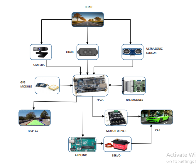
We, would like to use the features present in the FPGA platform for efficient working of the prototype. In our proposed design, we will be using DE-10 Nano FPGA board, Adasky viper(for input), 2 motor shields (cryton)(for controlling car speed), 12V battery(to energize car) and Arduino UNOcomponents.
Demo Video
Project Proposal
1. High-level project introduction and performance expectation
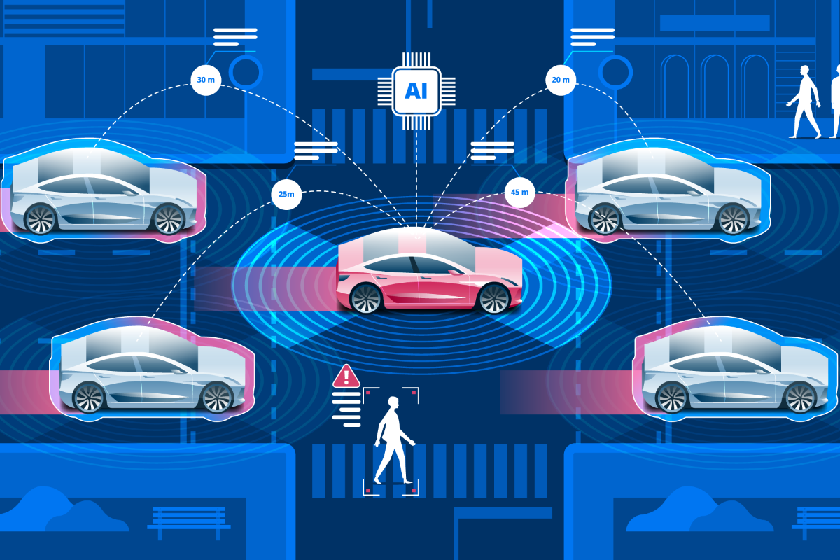
Now a days accidents are increasing due to negligence of people (Over speeding, Drunken driving, Distractions to driver, Red light jumping, Non-adherence to lane driving and overtaking in a wrong manner ). In order to reduce these causes for accidents, We designed a project named Autonomous car
It is already known that, a lot of research work is going on across the globe on design of autonomous vehicles/self-driving cars/driverless cars and few of them may become a reality soon on the roads. And popular prestigious companies like Tesla, Kia-Hyundai, Ford, Audi are on the race for manfacturing Autonomous cars. But, this technology will be appreciated when it will work with maximum efficiency and simultaneously when it is made available to the general public even.
In our proposal, we would like to design a prototype of self-driving car which uses machine learning algorithms and will fulfill the following objectives:
1. Collision Avoidance System
2. GPS based routing of vehicle
3. Lane Detection
4. Object/ Obstacle Detection
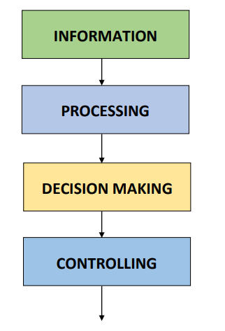
We are using DE-10 Nano FPGA board for lane detection as we used FPGA vision Sobel filter/edge detection algorithm on concept basis of Hough transform and SVM. We used FPGA for obstacle detection using Haar cascade algorithm. And we used FPGA for Global positioning system (GPS). FPGA analyses and process the input data that is recieved from sensors and camera and pass the control signals to Arduino. And Arduino controls the car with the help of Motor driver.
Purpose of the Design:
This plan spins around the idea of self-driving vehicles with the most recent innovation of FPGA. The focal thought behind this plan is to decrease the passing pace of people while going on streets. We might stay away from the wild fender benders, thoughtless driving, crummy choice taken by drivers, infringement of traffic rules and over speeding, and so forth Then again, in the forthcoming years, it is going to assume a pivotal part in the car business. This plan has the ability and usefulness with a wide scope of utilizations for any vehicle. Plan of our task can be utilized in various regions primarily on-street vehicles (i.e., car, truck, bus, and any other transportation vehicles).
Application Scope:
This thought has immense applications in different fields.
1. Modern transportation and products transportation turns out to be more available and more secure.
2. Automation can be utilized in different fields like cultivating and agri business, development and mining.
3. Physically handicapped people are free to access this car.
Targeted Users:
Now a days, Autonomous vehicles are having a great demand at Automobile industries. In our project we mainly focussed on real time specifications and we integrated Machine learning with FPGA into the field of Autonomous vehicles. Physically challenged people can access this car. It has a vast range of uses in Modern transportation and product transportation. And by integrating some detections it can be useful for Agriculture and Milatary applications also.
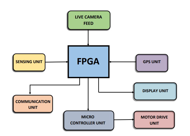
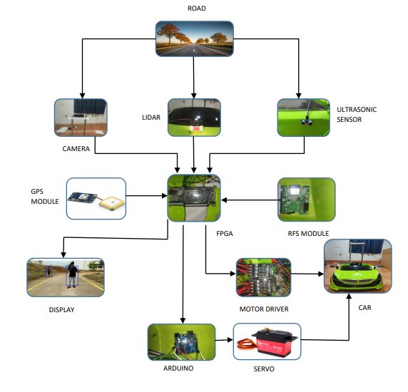
2. Block Diagram
3. Expected sustainability results, projected resource savings
Expected Sustainability results and Performance Parameters:
1. Collision Avoidance system: Our car should be able to avoid collison from moving objects or non moving objects. If any object detected with in a range of 150cm-300cm, Then it will adjust the path with respect to the detected object. In necessary condition car will stop and it will move with respect to the moment of the object. similarly collison may occur at the sides and back of the car due to the movement of objects from different directions. so our model will be able to avoid that type of collisons too, with in a range of 50cm-100cm.
2. GPS based routing of vehicle: Our car should be able to follow the path given by the user. As user gives the final destination point as input through Global positioning system (GPS). and our model has to find the best route and gives the distance information to the user as check points.
3. Lane detection: Our car should be able to follow the lanes. Genrally there are so many types of lanes present on the road such as single lane, double lane, dividers etc. and some roads may did not contain any lanes too. Hence our model has to predict all types of lanes and it should follow edge detection for the roads that did not contain lanes.
4. Object/ Obstacle detection: Our car should be able to detect Objects/ Obstacles. Generally there are many objects present or moving on the road. Our model should detect both moving and non moving objects and it will take the decisions for steer moving with respect to the distance and stability of objects. Similarly it should detect trafiic signals too.
Project Resource Savings:
1. As DE10 Nano FPGA Board is Dual core, So it is difficult to run multiple tasks. And primary problem is that our model have to detect both lanes and objects at a time and it has to take decisions based on those detections. And Image processing requires faster computation. So we kept both object detection and lane detection together using Multi threading. So we need not integrate another micro processor or micro controller to our model.
2. For Collison Avoidance System we interfaced both LIDAR (Light Detection and Ranging) and Ultrasonic sensor together. So it is easy to avoid collisons even in critical situations and circuit becomes simple.
4. Design Introduction
Purpose of the Design:
This plan spins around the idea of self-driving vehicles with the most recent innovation of FPGA. The focal thought behind this plan is to decrease the passing pace of people while going on streets. We might stay away from the wild fender benders, thoughtless driving, crummy choice taken by drivers, infringement of traffic rules and over speeding, and so forth Then again, in the forthcoming years, it is going to assume a pivotal part in the car business. This plan has the ability and usefulness with a wide scope of utilizations for any vehicle. Developed prototype can be utilized in various regions primarily on-street vehicles (i.e., car, truck, bus, and any other transportation vehicles).
We designed a self-driving car which uses machine learning algorithms and will fulfill the following objectives:
1. Collision Avoidance System
2. GPS based routing of vehicle
3. Lane Detection
4. Object/ Obstacle Detection
Components used for making Autonomous car:
1.DE10 Nano FPGA board
2. Intel cloud connectivity kit
3. Light detection and Ranging sensor (LIDAR)
4. Ultrasonic sensor (HC-SR04)
5. Camera
6. Arduino
7. Motor Driver
8. GPS Module
9. Servo motor
Application Scope:
This model has immense applications in different fields. Some major applications are listed below:
1. Modern transportation and products transportation turns out to be more available and more secure.
2. Automation can be utilized in different fields like cultivating and agri business, development and mining.
3. Physically handicapped people are free to access this car.
Targeted Users:
Now a days, Autonomous vehicles are having a great demand at Automobile industries. In our project, we mainly focused on real time specifications and we implemented Machine learning algorithms with FPGA into the field of Autonomous vehicles. Physically challenged people can access this car. It has a vast range of uses in Modern transportation and product transportation. By integrating some detection algorithms, our product will be useful for Agriculture and Milatary applications.
Virtues of DE10 Nano FPGA Board and Azure Cloud in our Project:
1.We have performed two main functionalities of Image Processing. They are Object detection and Lane detection which needs high computational power and fast processing. Image processing functionalities can be achieved with FPGA board which is having High speed 800- MHz Dual-core ARM cortex processor, which makes it possible to do complex processes .
2.The FPGA board has 2*40 GPIO header pins. 1 header is interfaced with RFS module other header used to interface Ultrasonic and Lidar sensors which plays a crucial role in distance sensing and in collision avoidance.
3.We used Azure cloud which acts as 2 way communication device which takes input from board and sends data to the website.
4.To perform all these activites parallelly, we have an onboard DDR3 1GB memory which helps to complete our tasks.
5. Functional description and implementation
Functional Description and Implementation:
System Flow Diagram:
1. Camera: By taking the live camera feed, we performed Object detection and lane detection through Hard Processor System (HPS) in DE10 Nano FPGA Board.
1.1 Object detection:
Object detection is a key component in the self-driving cars by combining with the sensors, which helps in decision making and motion control while ensuring the stability of the vehicle. In our design, we have implemented the object/human detection algorithm with pre-trained Haar-Cascade and Linear Support Vector Machine Model using Opencv Computer Vision library with python.
Our car should be able to detect Objects/ Obstacles. Generally there are many objects present or moving on the road. Our model should detect both moving and non moving objects and it will take the decisions for steer moving with respect to the distance and stability of objects.
.png)
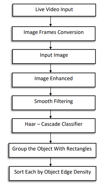
1.Live Video input: In our model, we have taken an input (Live Video feed) from the USB tethered Mobile camera, which connected to DE-10 Nano through OTG port.
2. Image Frames Conversion: Now, we converted the live Video feed to Images frames with a particular interval of time (10 frames per second).
3. Input image: Now our model will be able to take live video feed as image frames. And we convert the RGB formated image frames to Grayscale image frames with Grayscale conversion technique. Because Grayscale Format has low levels as compared to RGB format, and It is easy for model to detect objects.
4. Image Enhanced: After taking the image frames as input. We used image enhacement technique. The Python Imaging Library(PIL) adds powerful image processing capabilities. It provides immense file format support, an efficient representation, and fairly powerful image processing capabilities.Image enhancement is the process of adjusting digital images so that the results are more suitable for display or further image analysis. we remove noise in the image frames and similarly we sharpen and brighten the image frames with Image Enhancement.
5. Smooth Filtering:
5.1. Image smoothing is achieved by convolving the image with a low-pass filter kernel. It is useful for removing noise. It actually removes high frequency content from the image. So edges are blurred a little bit in this operation (there are also blurring techniques which don't blur the edges). OpenCV provides four main types of blurring techniques: Averaging, Gaussian Blurring, Median Blurring, Bilateral Blurring.
5.2. We used Gaussian Blurring technique for Smooth filtering as in this method, instead of a box filter, a Gaussian kernel is used. It is done with the function, cv.GaussianBlur() . We specified the width and height of the kernel which should be positive and odd. We also specified the standard deviation in the X and Y directions, sigmaX and sigmaY respectively. If only sigmaX is specified, sigmaY is taken as the same as sigmaX. If both are given as zeros, they are calculated from the kernel size. Gaussian blurring is highly effective in removing Gaussian noise from an image.
6.Haar-Cascade Classifier: Object Detection using Haar feature-based cascade classifiers is a machine learning based approach where a cascade function is trained from a lot of positive and negative images. It is then used to detect objects in other images. In our Project we used full body cascade to Humans and Contour detection to detect moving Objects.
7.Grouping object with Rectangles: We group the detected objects with rectangles.
8. Sorting each object by edge density: Now our primary objecive is to detect the objects that are under the FPGA vision and Our model has to give the priority for near objects with respect ot the Car. So we sorted each object by edge density. If edge density of the object is more, then our model will take decisions for moving with respect to object. If edge density of the object is less, then our model ignores the object.
1.2 Lane detection:
Lane detection is one of the primary element in our Autonomous car. Our car should take turnings with respect to lanes. Watching lane lines highlighted by the computer vision algorithm as the vehicle moves give a great joy of accomplishment. Detecting lane lines is indeed a very crucial task. It provides lateral bounds on the movement of the vehicle and gives an idea about how much deviated, the car is from the center of the lane. Lane detection relies only on camera images. We apply computer vision techniques to process the image and give lane markings as the output. We have used the OpenCV library to implement the Lane Detection Algorithm. Based on detected lane output we build the path planning algorithm.
Data flow for Implementation of the Lane Detection:
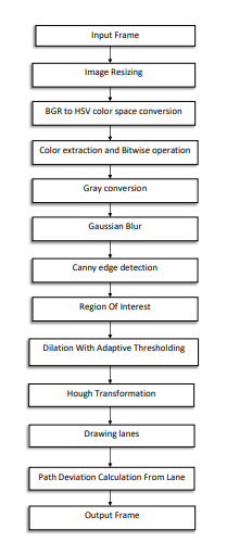

1. Input Frame : In our model, we have taken an input (Live Video feed) from the USB tethered Mobile camera, which connected to DE-10 Nano through OTG port.
2. Image resizing: Resize the input image for optimized processing and convenient display. In our algorithm, we have resized the image into a 640 x 480 resolution.
3. BGR to HSV Color space conversion: BGR color space describes the colors of the image in terms of the amount of blue, red, and green present. HSV color space describes colors in terms of Hue, Saturation, and Value of the image. We require a better representative model of color, and hence, we have the HSV space.
4. Color Extraction and Bitwise Operation: Extract desired colors from HSV converted image with BGR upper and lower threshold values. Make a mask with the above-extracted output. Now, perform bitwise operations to delete the unnecessary part in the original image using a mask. It results the image with our desired color ranges. In our case, we have extracted the yellow color on the road dividers and deleted the remaining unnecessary colors
5. Gray conversion: It converts the extracted image into grayscale. Color increases the complexity. The luminance of a pixel value of a grayscale image ranges from 0 to 255. It reduces the ambiguity and complexity of multiple pixel values of colors: from a 3D pixel value (R, G, and B) to a 1D value. It is very useful when dealing with image segmentation, thresholding, and edge detection
6. Gaussian Blur: In image processing, a Gaussian blur (Gaussian smoothing) is the result of blurring an image and removing noise by a Gaussian function. In Gaussian Blur operation, the image is convolved with a Gaussian filter. The Gaussian filter is a low-pass filter that removes the high-frequency components. It is nothing but using different weight kernel, in both the x and y directions. A kernel is nothing more than a array of pixels. The standard deviation of the Gaussian determines the degree of smoothing. The Gaussian outputs a weighted average of each pixel's neighborhood, with the average weighted more towards the value of the central pixels. Gaussian provides gentler smoothing and preserves edges better than a similarly sized mean filter. In our case, we have applied Gaussian smoothing for better edge detection.
7. Canny edge detection: The Canny edge detector is an edge detection operator that uses a multi-stage algorithm to detect a wide range of edges in images. The Canny edge detection algorithm is composed of four steps.
7.1. Noise reduction: First step is to remove the noise with a 5x5 Gaussian filter
7.2. Gradient Calculation: Smoothened image is then filtered with a Sobel kernel in both horizontal and vertical directions to get the first derivative in the horizontal direction (Gx) and vertical direction (Gy). From these two derivatives, we have calculated the edge gradient and direction for each pixel.
7.3. Non-Maximum Suppression: After getting gradient magnitude and direction, a full scan of an image is done to remove unwanted pixels that may not constitute the edge. For this, at every pixel, a pixel is checked it is a local minimum in its neighborhood, in the direction of the gradient.
7.4. Hysteresis Thresholding: This stage decides which all edges are and which are not. For this, we need two threshold values, minimum and maximum values. Any edges with intensity gradients more than maximum value are sure to edge and those below minimum values are sure to be non-edges, so discarded. Those who lie between these 2 values are classified as edges or non-edges based on their connectivity
8. Region of Interest Selection: We need to avoid the unnecessary edges to plot the Hough line transforms. By performing Arithmetic operations on the image, we can get the interested and optimized selected area to plot the lane
9. Dilation with Adaptive Thresholding: Dilation is one of the Morphological operations, that apply a structuring element to an input image and generates an output image. Here, the binarized ROI image is given as an input to be dilated with a structuring element of 5 × 5 kernels to fill the gaps and to remove small random variations. Dilation adds pixels to the boundaries of detected objects in an image. To make the image binarization, we have used the Adaptive Thresholding method, which calculates the threshold for smaller regions of images. It gives better results of images with varying illumination. The process of binarization is starting with image division into small strips and then applying the global threshold to each strip
10.Hough Transform: Hough transform is a feature extraction method for detecting simple shapes such as circles, lines, etc., in an image. To Increase the computing speed without losing much accuracy, we have decided to work with the Probabilistic Hough transform. The algorithmic flow of the Hough transform is as follows:
10.1. Edge detection, e.g. using canny edge detector.
10.2 . Mapping of edge points to the Hough space and storage in Accumulator.
10.3. Interpretation of the accumulator to yield infinite lines of length. The interpretation is done by thresholding and possibly other constraints.
10.4. Conversion of infinite lines to finite lines. We have considered some parameters and passed to this Hough transform are dilated image, distance resolution of the accumulator in pixels as a rho, angle resolution of the accumulator in radians as a theta, threshold for the accumulator, the minimum length of the line and the maximum gap between the lines.
11. Drawing Lanes: From the points of detected lines in Hough Transform, we have drawn the lane lines with geometric shapes on the image
12. Path Planning: It’s a very crucial and final step in the lane detection algorithm as well as for path planning. We have to decide and stabilize the position of the vehicle based on the lane on the road. Here we have measured the distance from horizon to top on both sides left and right. We have measured the distance from the horizon of the image to lane’s lowest coordinate point, let left distance be DL and right distance be DR and calculated the difference from DL and DR. After many trials using trial and error method we have set one threshold of difference for decision making to steer and to balance the stable position of the vehicle on the road. This threshold decides the accuracy of path plan. As the extracted road region is approximate, consider a tolerance limit of Delta.
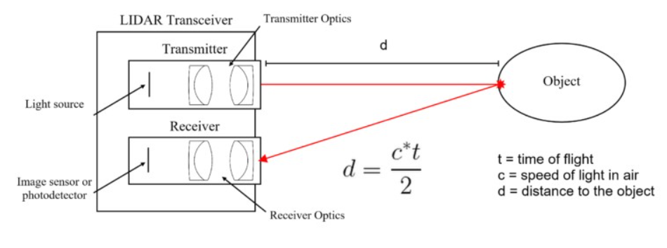
2.TF MINI LIDAR:
The LiDAR works on the principle of “Time of Flight”. It uses ultraviolet, visible or near-infrared sources to sense objects. The light energy emitted by the LiDAR is known as Pulse and the reflected light from the object is know as return. The LiDAR system sends pulse and waits for the pulse to return. It measures how long it takes for emitter pulse to return back to the sensor. In the end it gets the variable distance of the objects.
The equation that used to show up at the exact distance of the object is as per the following:
Distance = [(Speed of Light) x (Time of Flight)] ÷ 2
3. Ultrasonic Sensor:
1. An ultrasonic sensor is an instrument that measures the distance to an object using ultrasonic sound waves.
2. An ultrasonic sensor uses a transducer to send and receive ultrasonic pulses that relay back information about an object’s proximity.
3. The working principle of this module is simple. It sends an ultrasonic pulse out at 40 kHz which travels through the air and if there is an obstacle or object, it will bounce back to the sensor. By calculating the travel time and the speed of sound, the distance can be calculated. For presence detection, ultrasonic sensors detect objects regardless of the color, surface, or material.

We will call the time to transmit and receive is known as Time of Flight. By this time of flight we can find distance by using below formula:
Speed of sound = 29us /cm (in room temp)
Time of Flight = T0
Range =Time of Flight / (2*Speed of Sound)
4. GPS Module:
In our project GPS routing also plays a crucial role where the car needed to follow a specified path given by user.
For GPS routing we are using azure map services and current GPS location of the car. Azure map services is one the features in azure IOT edge. We are using an API which consider two coordinates that are starting and the end point of the required location. By using the get request we can obtain GPS points in between the given two previous coordinates. The get request will also gives the total count of the coordinates in between starting and the ending positions, and it points the exact location. From Azure maps we get the coordinates from current to destination location, these set of coordinates will be sent to the FPGA Board there the board checks and gives the instruction to the car to moves from current coordinate to the nearest coordinate from the set of coordinates given by the Azure map this process continues until the car reaches the destination. The set of coordinates given by the azure maps is our checkpoints, after reaching each checkpoint, the map will be updated in Website.
5. RFS Module:
Cloud computing:
Cloud computing is a platform that provides access to the computing resources over the internet.
Cloud providers own massive datacenters which have hundreds of servers, storage systems and components critical to the organization’s working.
Cloud computing is used for the following types of services:
1.Creating and testing applications
2.Hosting blogs and applications
3.Machine learning and data analysis
4.Data storage and backup
5.Streaming media content
6.Automating software delivery etc.
Microsoft Azure is a cloud computing service provided by Microsoft.
It is actually an online portal through which we can access and manage resources and services.
It supports wide variety of languages like C++, Java, Python etc.
We can handle events easily through internet and Azure IOT hub is reliable for IoT integrated technologies.
How we are using Azure cloud for our project?
1.In our project, we use Azure cloud for monitoring sensor and Radar data, situation of the car premises, and GPS locations.
2.Azure services plays crucial role in our project, without azure VM services we are unable to host our website.
3.Azure IoT Hub also used for us to store RFS details which is used in determination of vehicle status and the motion condition and for estimating the angle of curve rotating.
6. DE10 Nano FPGA Board:
DE10 NANO board is the main processing and controlling unit of the system. To work all processes and parallel works we have ARM cortex Processer and DDR3 memory. For car position and sensor details values comes from RFS module. Board 2 gpio header , so in that 1 header will goes to RFS and for one header we will send control signals to motor drivers , send signals and receive data from our sensors. Based on the Lane detection and collision detection the steering of the vehicle is changed. From gps module the current coordinates of the car taking into board.
The detections and data coming from the board will be sent to cloud by the FPGA board, from there the data will be transmitted to the website where it displaying the RFS data, Detections and location of the car.
7. Motor Driver:
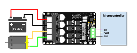
1. We used MD20A motor drivers for vehicle movement , The MD20A takes 6-30 V DC power supply and by control signals the motors will run.
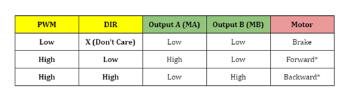
2. Motor Driver has 3 control pins which acts as a micro controller and those are PWM(pluse width Modulation), Ground and Direction pin.
3. By giving control signals as 0 or 1 we can run our motors in forward direction or reverse direction or full speed or stopping all thesre can be done by this driver.
4. For supply we gave external power supply to motor driver and as for control signals the input came DE10 NANO FPGA board.
5. When there is no objects in collison range the board will give 1 as PWM and direction 0 , So the car moves forward, If it is in collison range the PWM becomes 0 and car stops.
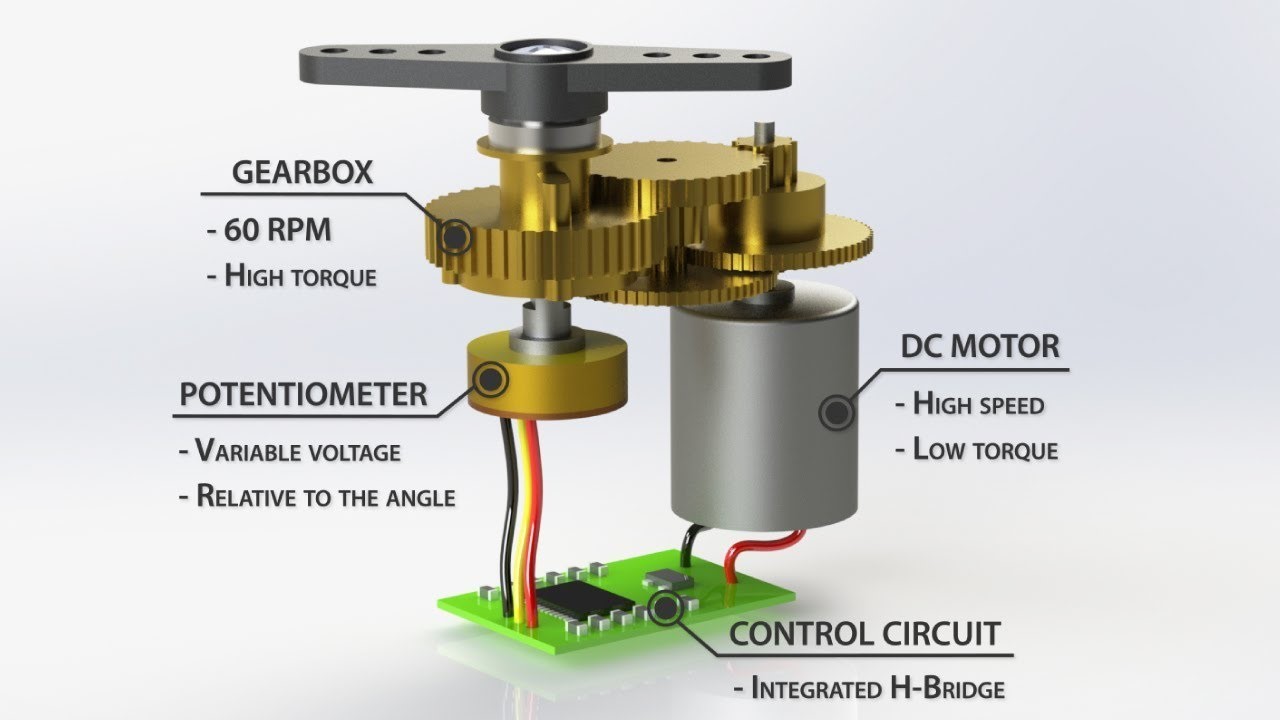
8. Servo motor:
- Servo motor high precision motors which have a high accuracy over angles and feedback system.
- The function of the servo motor is to convert the control signals into rotational angular displacement of the motor shaft.
- In our project we need a high precision angles for steering control so we used servo. The servo has 3 pins , VCC,Ground,PWM. By the width of the PWM we can control the angle of the servo.
- For the purpose of high precision width of PWM we gave PWM from arduino. By giving control signals to ardunio we can control the servo whenever it need to turn.
By this servo we steer our vehicle left or right with high precison.
6. Performance metrics, performance to expectation
1. Collision Avoidance system: Our car is abled to avoid collison from both moving objects and non moving objects. If any object detected within a range of 150cm -300cm, Then it will adjust the path with respect to the detected object. In necessary condition car will stop and it moves with respect to the moment of the object. Our model avoided collisons that occur at the sides and back of the car due to the movement of objects from different directions with in a range of 50cm-100cm.
2. GPS based routing of vehicle: For GPS routing we are using azure map services and current GPS location of the car. Azure map services is one the features in azure IOT edge. We are using an API which consider two coordinates that are starting and the end point of the required location. By using the get request we can obtain GPS points in between the given two previous coordinates. The get request will also gives the total count of the coordinates in between starting and the ending positions, and it points the exact location. From Azure maps we get the coordinates from current to destination location, these set of coordinates will be sent to the FPGA Board there the board checks and gives the instruction to the car to moves from current coordinate to the nearest coordinate from the set of coordinates given by the Azure map this process continues until the car reaches the destination. The set of coordinates given by the azure maps is our checkpoints, after reaching each checkpoint, the map will be updated in Website.
3. Lane detection: Our car is abled to follow the lanes. Our model is predicting all types of lanes and it follows edge detection for the roads that did not contain lanes too.
4. Object/ Obstacle detection: Our car is abled to detect Objects/ Obstacles. Generally there are many objects present or moving on the road. Our model is detecting both moving and non moving objects and it takes the decisions for steer moving with respect to the distance and stability of objects.
Project Resource Savings:
1. As DE10 Nano FPGA Board is Dual core, So it is difficult to run multiple tasks. And primary problem is that our model have to detect both lanes and objects at a time and it has to take decisions based on those detections. And Image processing requires faster computation. So we kept both object detection and lane detection together using Multi threading. So we need not integrate another micro processor or micro controller to our model.
2. For Collison Avoidance System we interfaced both LIDAR (Light Detection and Ranging) and Ultrasonic sensor together. So it is easy to avoid collisons even in critical situations and circuit becomes simple.
Virtues of DE10 Nano FPGA Board and Azure Cloud in our Project:
1.We have performed two main functionalities of Image Processing. They are Object detection and Lane detection which needs high computational power and fast processing. Image processing functionalities can be achieved with FPGA board which is having High speed 800- MHz Dual-core ARM cortex processor, which makes it possible to do complex processes .
2.The FPGA board has 2*40 GPIO header pins. 1 header is interfaced with RFS module other header used to interface Ultrasonic and Lidar sensors which plays a crucial role in distance sensing and in collision avoidance.
3.We used Azure cloud which acts as 2 way communication device which takes input from board and sends data to the website.
4.To perform all these activites parallelly, we have an onboard DDR3 1GB memory which helps to complete our tasks.
7. Sustainability results, resource savings achieved
Sustainability results:
For obstacle detection our car is abled to detect Objects/ Obstacles. We detect humans by using human cascade classifier. Generally there are many objects present or moving on the road. Our model detected both moving and non moving objects and it takes the decisions for steer moving with respect to the distance and stability of objects.
For Lane detection our car is abled to follow the lanes. For lane detection we used Hough Transform Principle, support vector machine (svm) and Gaussian blur technique. Our model is predicting all types of lanes and it follows edge detection for the roads that did not contain lanes too.
For collision avoidance we are mainly using lidar and ultrsonic sensor. We will fix a specific range for the collision detection and trigger the ultrasonic sensor. If the left ultrasonic have less distance than threshold and right have more distance then the car will steer to right. If right have less distance and right have more than threshold distance then it will move to left. If there is no persons in threshold range then it will depend on lane controls. If no distance avalable for avoidance then car will stop.
In our project GPS routing also plays a crucial role where the car needed to follow a specified path given by user.
For GPS routing we are using azure map services and current GPS location of the car. Azure map services is one the features in azure IOT edge. We are using an API which consider two coordinates that are starting and the end point of the required location. By using the get request we can obtain GPS points in between the given two previous coordinates. The get request will also gives the total count of the coordinates in between starting and the ending positions, and it points the exact location. From Azure maps we get the coordinates from current to destination location, these set of coordinates will be sent to the FPGA Board there the board checks and gives the instruction to the car to moves from current coordinate to the nearest coordinate from the set of coordinates given by the Azure map this process continues until the car reaches the destination. The set of coordinates given by the azure maps is our checkpoints, after reaching each checkpoint, the map will be updated in Website.
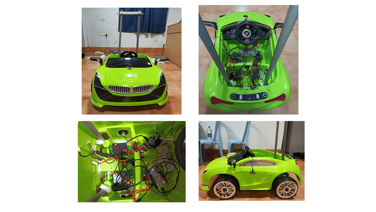
System design scheme:
Hardware Design Block:
Resource savings achieved:
1. As DE10 Nano FPGA Board is Dual core, So it is difficult to run multiple tasks. And primary problem is that our model have to detect both lanes and objects at a time and it has to take decisions based on those detections. And Image processing requires faster computation. So we kept both object detection and lane detection together using Multi threading. So we need not integrate another micro processor or micro controller to our model.
2. For Collison Avoidance System we interfaced both LIDAR (Light Detection and Ranging) and Ultrasonic sensor together. So it is easy to avoid collisons even in critical situations and circuit becomes simple.
8. Conclusion
Conclusion:
We have implemented an efficient and reliable real-time prototype of autonomous car with features of lane detection, object detection, distance measurement, GPS Tracking and Collision Avoidance System. This system accurately takes quick decisions in accordance with the surroundings. We have also implemented Detections monitoring system and car control monitoring system using Microsoft Azure Cloud.
References:
1. https://docs.opencv.org/4.x/
2. https://docs.opencv.org/3.4/d9/db0/tutorial_hough_lines.html
3. https://docs.opencv.org/3.4/db/d28/tutorial_cascade_classifier.html
4. https://docs.opencv.org/3.4/d2/d2c/tutorial_sobel_derivatives.html
5. https://scikit-learn.org/stable/modules/svm.html
6. https://www.terasic.com.tw/cgi-bin/page/archive.pl?Language=English&CategoryNo=167&No=1046
7. https://rocketboards.org/foswiki/Documentation/DE10NanoDevelopmentBoard
8. https://www.elecrow.com/download/TF-MINI-LIDAR-USER-MANUAL.pdf 5.
9. https://www.pantechsolutions.net/uart-communication-with-spartan3an-fpga-project-kit 6.
10. https://www.electronoobs.com/eng_circuitos_tut26.php
1 Comments
Please login to post a comment.
Bahadir
Hi,
Can you share source code of project with me?