Plastic pollution has become one of the most pressing environmental issues, as rapidly increasing production of disposable plastic products overwhelms the world’s ability to deal with them. Plastic pollution is most visible in developing Asian and African nations, where garbage collection systems are often inefficient or nonexistent. But the developed world, especially in countries with low recycling rates, also has trouble properly collecting discarded plastics. Plastic trash has become so ubiquitous it has prompted efforts to write a global treaty negotiated by the United Nations.
Did you know that every plastic that is being produced in the world still exists today? Half of all plastics ever manufactured have been made in the last 15 years.Millions of animals are killed by plastics every year, from birds to fish to other marine organisms. Nearly 700 species, including endangered ones, are known to have been affected by plastics. Nearly every species of seabird eats plastics.There is no natural process to degrade plastic but we can recycle them.so, we wanted to design our bot to collect and dump them into the trash.
Demo Video
Project Proposal
1. High-level project introduction and performance expectation
Our design contains mainly three tasks. Those are data gathering, Decision making or processing and controlling.
We are going to implement our project with the help of some machine learning algorithms. At first, we will train our bot in such a way that it can be able to identify PET bottles and polythene covers. For detection purposes, we are using a small camera placed in front of the bot. We use the FPGA board for decision-making and information gathering purposes. After detection, our bot will reach the place where those plastic items are present. We are using ultrasonic sensor to measure the distance between the bot and the plastic. After measuring the distance, the FPGA board will send the information to the Arduino microcontroller that drives the motors to move forward. After reaching there, our bot has to pick the object. For picking purposes, we are placing an arm that consists of motors that are going to be driven by the rasp-pi board. After Picking, our bot will dump those items into the bin.
We will use the FPGA Cloud connectivity kit to collect, analyze and react to data from the image captured by the camera. In our case, it is plastic. After detection, it has to reach that destination. To monitor our bot, we are using the Microsoft Azure cloud platform. We will connect our FPGA board to the Azure cloud to track the location of our bot via GPS. Our camera will also identify whether the trash can is full or empty. If the bin is full, it immediately sends the information to the cloud where we can access it to take any further steps. We are using the Intel FPGA kit because Intel is dedicating to providing higher performance in all its forms and the FPGAs are an important part of that strategy. Intel FPGA's are reconfigurable and provide more flexibility to the users at a lower cost.
Task 1: Gathering data
In this task, our bot needs to collect the image for further processing. We also need the information regarding whether the bin is full or empty. If the trash can is not empty, our bot will send the information to the cloud, so that we can access the status of the bin. To detect the plastic, We will train our model with large data sets using machine learning algorithms to identify images.
Task 2: Decision making or processing
After detection, it has to reach the place where those plastic items are being present. We will set a particular range for the bot to identify those items. If there is more than one bottle at a single location, we will set priority based on the image. So, that it will be able to focus on a single item.
After detection, it tries to manipulate the distance between the bot and the plastic to reach the point where the distance between the bot and the plastic is equal to the arm distance for proper picking. If our bot encounters any obstacle, it stops there itself.
In order to search for plastic.Our bot has to rotate and manuever. For that we are placing a servo motor underneath the camera which can be able to identify in a given range. If the trash can is full of garbage, it immediately sends us the information. As these are solid waste, we will set a limit up to how much it can store. If the limit exceeds, it immediately sends us the data. Here comes the main task, which is monitoring. For monitoring purposes, we need to develop a control system.we are going to track the bot movements using the GPS module and with the help of Azure cloud.
Task 3: Arm and motor controlling
For picking purposes, we are using an end effector which is connected to the end of a robot arm where the hand would be. An arm is constructed with a bunch of servo motors, with the help of servos we will control the arm movement. For better accuracy, we are using controllers. Using feedback to make a closed-loop system and getting a preliminary insight from this system step response. we will design controllers to control the robotic arm system to meet system requirements.For chasis motor control, we are using motor drivers that will be interfaced with the DE10 nano board.
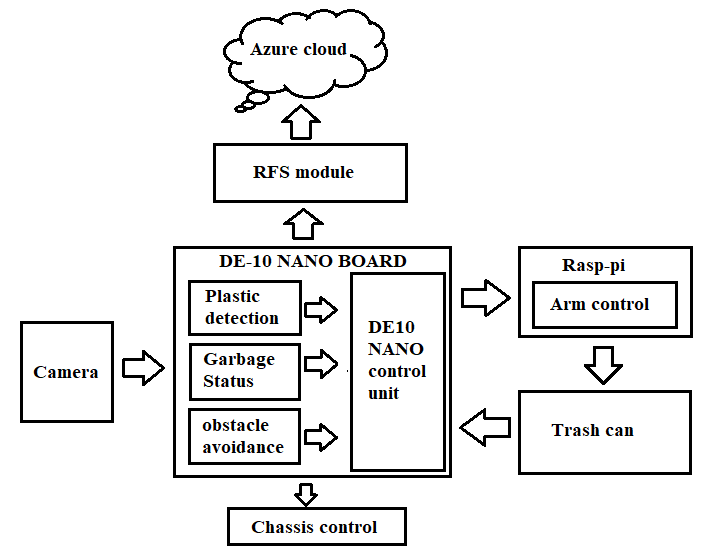
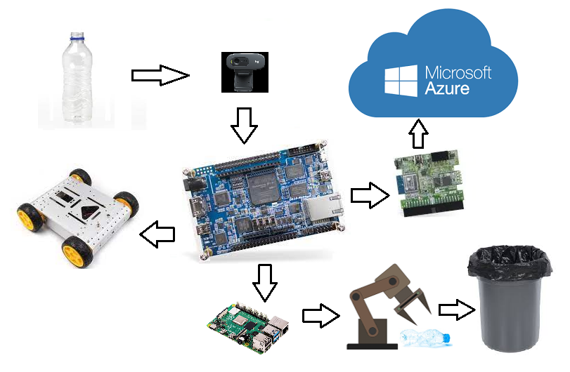
2. Block Diagram
3. Expected sustainability results, projected resource savings
Our bot can be able to detect a single bottle at a time. For a 180-degree vision span, we are placing a servo motor underneath the camera. While rotating, if it identifies an item, the rotation stops, the FPGA sends the information to the motor drivers that drives the bot to reach that point. After reaching there, it starts picking those items and throws them into the bin.Bin is included in our bot. Our bot can be able to pick empty bottles only.
This project is mainly concerned with a clean environment. Our bot helps to make the city clean. We will provide an enable button to start functioning. We will control this switch wirelessly. For charging purposes, we will include a battery in the bot itself. At last, our bot can be able to
→ Identify the plastic items.
→ Navigate properly without any malfunction.
→ Tries to pick the bottle/covers one by one.
→ Send the current status of the bot via the cloud.
→ Finally, it will dump those items in the bin
4. Design Introduction
PURPOSE OF THE DESIGN:
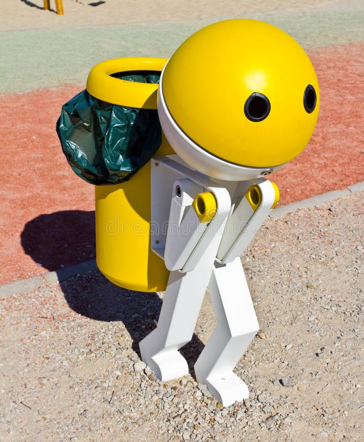
The main purpose of our project is to introduce a way in which garbage could be collected and disposed efficiently. To analyse the problem of garbage disposal at a school, restaurant, office, hotel, production plant or any other suitable location, we want to design and develop a prototype of a system for solving this problem. By this we can reduce plastic pollution to some extent. Here in our project, we want to develop a rag picking bot that collects plastic bottles. Since plastic bottles are becoming one of the major plastic pollution now-a-days, we are developing a rag picking bot that can collect plastic bottles only.
APPLICATIONS:
Technology is developing day by day. The same thing goes with the robots.In fact, robots have a wide range of applications in almost all industries these days because of their precision and convenience. Maintaining a proper garbage management is necessary to make a city hygienic. In fact, our bot can be useful to maintain proper garbage management in smart cities. Since our bot is autonomous, there is no need of human assistance. Because of this our bot can find a lot of applications related to garbage management at schools, restaurants, offices, hotels etc.
TARGET USERS:
In our project, we specifically focused on real-time features associated with implementation of Autonomous robots which is a major concern today. Since, our main focus is on garbage management, target users are garbage management workers. It also find a vast range of applications for industrial purposes.
DESIGN INTRODUCTION:
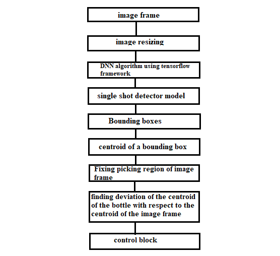
fig:1 Flowchart of our design algorithm
Image frame:
At first we have taken an input frame (Live Video stream) from C270 webcam, which is connected to DE-10 Nano through OTG port
Image resizing:
Resize the input image for optimized processing and convenient display. In our algorithm, we have resized the image into a 640 x 480 resolution.
DNN algorithm using tensorflow frame work:
We have used tensorflow which is an open source framework. It supports deep neural network algorithm which we have used to create multiple layers of neural networks for better optimization of detection model.
Single shot detector model:
We have trained SSD model on bottle dataset to detect the bottle with an accuracy of 85% and above. The SSD model works as follows, each input image is divided into grids of various sizes and at each grid, the detection is performed for different classes and different aspect ratios. And a score is assigned to each of these grids that says how well an object matches in that particular grid.
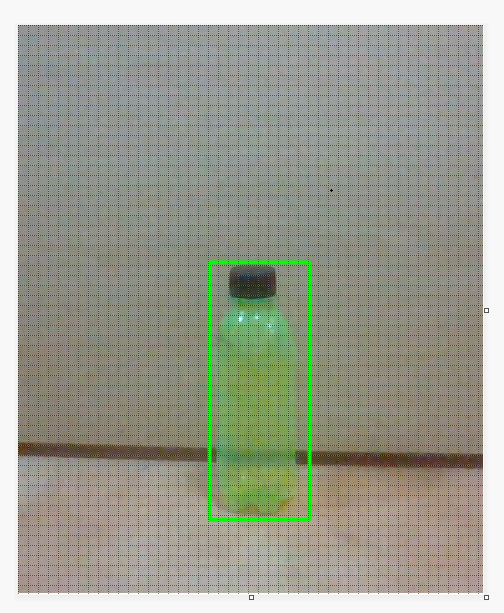
Bounding boxes:
Whenever the bottle is detected, a bounding box is created. Based on the bounding box, we can classify the bottle image with the other images.
Centroid of a bounding box:
We have calculated the centroid of the bounding box to know the exact deviation of the bottle image frame form the centroid of the actual image frame. Here in our case, the centroid of the image is located at (320,240) as our captured image is of 640x480p
Fixing picking region of image frame:
Here we have created a fixed image frame which is of (100 ,60) pixels wide. Whenever the centroid of the bottle frame is present inside this frame, our bot starts picking that bottle.
Finding deviation:
In this, we have calculated the exact deviation of the centroid of the bottle frame and the centroid of the fixed frame using the formula
Deviation = ((Cx – Bx)^2 + (Cy - By)^2 )^(0.5)
This is simply the distance between two centroids. Here (Cx,Cy) indicates the fixed centroid and (Bx,By) indicates the centroid of the bottle frame. Based on this deviation, Bot speed is controlled.
Control block:
Based on the above deviation, bot speed is controlled. Whenever the centroid of the bottle frame is present inside fixed middle frame, two arms start picking the bottle. Arms are controlled by the servo motors.
Sending status to the cloud:
After picking the bottle, it sends that information to the cloud. Based on the limit set by the user, Bot will send the bin status to the cloud. Here we are using Azure cloud to monitor the bin status. Azure cloud will be interfaced with DE10 nano via RFS module.
5. Functional description and implementation
Our design is divided into 3 categories. They are
1. PLASTIC BOTTLE DETECTION:
As for the autonomous vehicles, the visual information is an important part in the whole system designing, which needs the high efficiency and instantaneity of information detection and recognition .This project uses Bottle dataset as training data to train the model, the SSD TensorFlow as target detection framework .
Single-Shot Detector (SSD):
The SSD model is made up of 2 parts namely
1.The backbone model
2.The SSD head.
1.1) The backbone model:
The Backbone model is a typical pre-trained image classification network that works as the feature map extractor. Here, the final image classification layers of the model are removed to give us only the extracted feature maps.
1.2) Feature extraction:
Backbone model trains on the bottle dataset to extract features. After going through a certain of convolutions for feature extraction, we obtain a feature layer of size m×n (number of locations) with p channels For each location, we get k bounding boxes. These k bounding boxes have different sizes and aspect ratios. The concept is, maybe a vertical rectangle is more fit for human,
and a horizontal rectangle is more fit for car.The SSD model works as follows, each input image is divided into grids of various sizes and at each grid, the detection is performed for different classes and different aspect ratios.And a score is assigned to each of these grids that says how
well an object matches in that particular grid. And non maximum suppression is applied to get the final detection from the set of overlapping detections. This is the basic idea behind the SSD model.
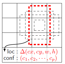
The default bounding boxes are associated with every feature map cell at the top of the network. These default boxes tile the feature map in a convolutional manner such that the position of each box relative to its corresponding cell is fixed.
For each box out of k at a given location, c class scores are computed and 4 offset relatives to the original default box shape. This results in the total of (c+4)k filters that are applied around each location in the feature map, yielding (c+4)kmn outputs for a feature map of size m x n.
LOSS FUNCTION:
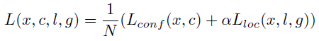
The loss function consists of two terms: Lconf and Lloc where N is the matched default boxes. Matched default boxes.
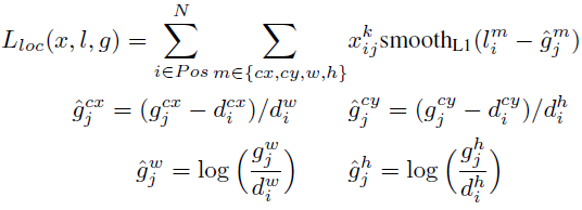
LOCALIZATION LOSS
Lloc is the localization loss which is the smooth L1 loss between the predicted box (l) and the ground-truth box (g) parameters. These parameters include the offsets for the center point (cx, cy), width (w) and height (h) of the bounding box.
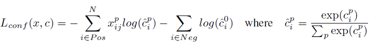
CONFIDENCE LOSS
Lconf is the confidence loss which is the softmax loss over multiple classes confidences (c). (α is set to 1 by cross validation.) xij^p = {1,0}, is an indicator for matching i-th default box to the j-th ground truth box of category p.
2.THE SSD HEAD
We are thus left with a deep neural network that is able to extract semantic meaning from the input image while preserving the spatial structure of the image albeit at a lower resolution. A neural network consists of several connected units called nodes. These are the smallest part of the neural network and act as the neurons in the human brain. When a neuron receives a signal, it triggers a process. The signal is passed from one neuron to another based on input received. A complex network is formed that learns from feedback.
The nodes are grouped into layers. A task is solved by processing the various layers between the input and output layers The SSD head is just one or more convolutional layers added to this backbone and the outputs are interpreted as the bounding boxes and classes of objects in the spatial location of the final layers activations.
2.AZURE CLOUD ACCESS:
After picking the bottle, our bot sends that information to the cloud. So, that we can monitor the bin status. From that we can confirm whether the bin is full or empty. Our bot also sends its present GPS location so, that we can monitor the bot’s location without any problem.
Here we are using azure cloud to monitor the bot’s status. We have interfaced the azure cloud with HPS of DE10 nano via RFS module. We have used Azure-storage-blob which is a client library for python. First we have created a storage account named “ragpicker” on azure cloud. Thereafter we have created a container for file storage. Inside that we can find the bot’s status inside the .txt file as shown in the fig below.
.png)
fig 2.1
In the above picture, you can easily monitor the bin’s status. To access it from DE10 nano, we have to install azure-blob-storage via LX-terminal. Using that library, we can send any text data from DE10 nano to the cloud.
Whenever the bottle is picked, rasp pi triggers the GPIO pin of DE10 nano. Whenever the GPIO pin goes high, it calls the .txt file and store the text message “bottle picked” and send that file to the cloud. After receiving the .txt file from DE10 nano, it displays the information.
Here is the webpage that we have devloped
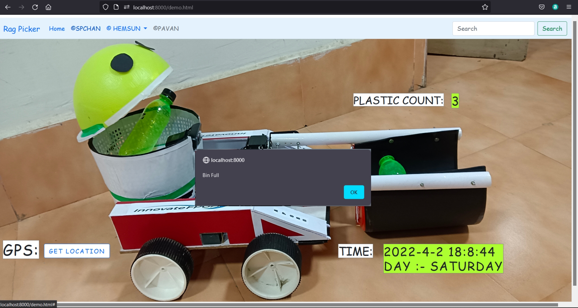
fig 2.2
Here GPS displays the location and the plastic bottle count will be displayed at the top right corner.So whenever the count exceeds 3, it gives an alert. Here we have considered only 3 bottles because our bot cannot hold more than 3 bottles.
3.BOT CONTROL MECHANISM:
This is the implementation part of our design. Here we have controlled our bot based on the commands given by the GPIO pins of DE10nano HPS.
3.1) BOT DECISION MAKING CONTROL:
While capturing the video, whenever the bot detects the plastic bottle, it first divides the captured video frame into 5 segments as shown in the figure below
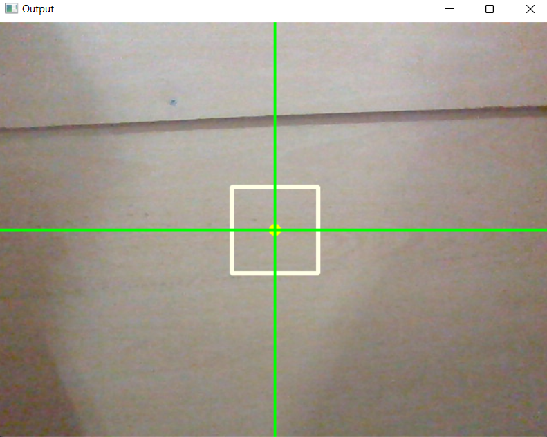
As you see in the above picture, we have plotted two lines. The intersection point represents the centroid of the captured video frame. We have also plotted a fixed bounding box located at the center of the video frame.
Whenever our bot detects the plastic bottle, it immediately creates a bounding box that fits the plastic bottle. Thereafter, it finds the centroid of that bounding box. Based on the centroid co-ordinates, our bot can be able to make the decision to move in a particular direction. Our main motto is to place the centroid point of the captured bottle frame inside the fixed bounding box located at the center of the captured image frame. If this happens, our bot will be in a right place to pick that bottle. All these operations are shown below.
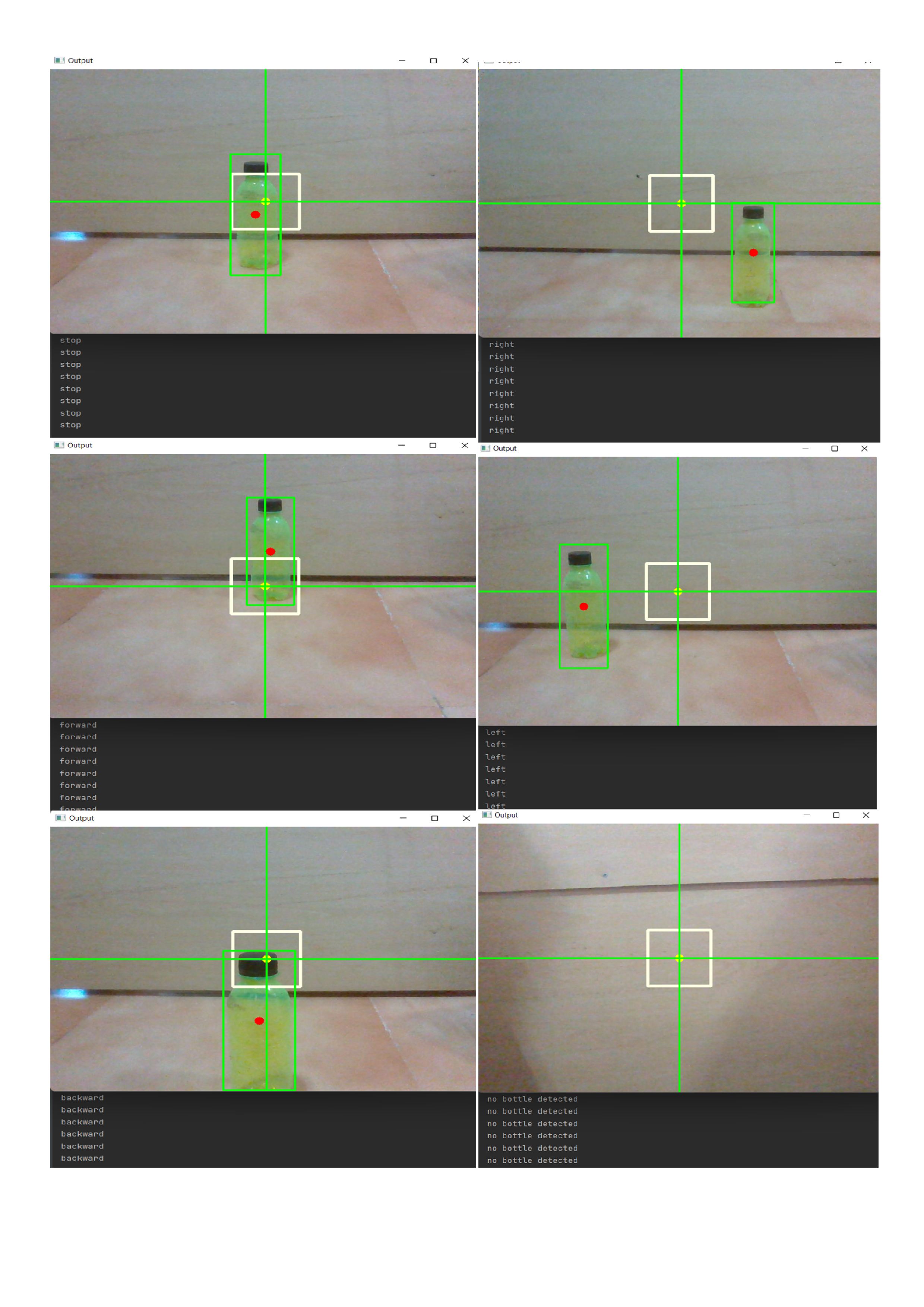
Case-1: If the centroid of the plastic bottle frame is located inside the fixed bounding box, “stop” command will be executed . After the execution of stop command, bot will be stopped.
Case-2: If the centroid of the plastic bottle frame is located directly above the fixed bounding box, “forward” command will be executed and then the bot will move forward
Case-3: If the centroid of the plastic bottle frame is located directly below the fixed bounding box, “backward” command will be executed and then the bot will move backward
Case-4: If the centroid of the plastic bottle frame is located towards right of the fixed bounding box, “right” command will be executed and then the bot will move towards right.
Case-5: If the centroid of the plastic bottle frame is located towards left of the fixed bounding box, “left” command will be executed and then the bot will move towards left.
Case-6: If no bottle is detected, it prints "no" and then it starts turning left to search for bottles that are out of the frame.
All the above cases are shown below
 3.2) ARM CONTROLLING:
After completing the above mentioned tasks, our bot will pick the plastic bottle. We have used MG995 servo motors to build the arm for picking purpose. Our arm is based on 2-DOF (degrees of freedom). Upper section of the arm contains two servo motors that is used to sweep the bottle (i.e., holds the bottle) and the below section of the arm also contains two servo motors, that is used to lift the bottle and throw it in the bin.
Left and right sections of the arm needs to be synchronized to pick the bottle properly. Or else it can’t pick the bottle properly. We have categorized each section of the arm into two sections
For Right arm:
1. Right up: Upper part of the right arm moves from 90 to 0 degrees and from 0 to 90 degrees. At first it will be in 90 degree position. Later whenever it need to pick, it rotates from 90 to 0 degrees.
2. Right down: below part of the right arm also starts from 90 degrees and rotates up to 15 degrees to reach the exact position. After that it rotates from 15 to 90 degrees to throw the bottle in the dust bin.
For left arm:
1. Left up: Upper part of the right arm moves from 0 to 90 degrees and from 90 to 0 degrees. At first it will be in 0 degree position. Later whenever it wants to pick, it rotates from 0 to 90 degrees. The operation of the left upper servo motor is opposite to the upper part of the right servo motor.
2. left down: below part of the left arm starts from 90 degrees and rotates up to 15 degrees to reach the bottle. After holding the bottle, it rotates form 15 degrees to 90 degrees to throw the bottle in the dust bin.
Lower section of both the left arm and right arm needs to be synchronized.
3.3) DE10NANO GPIO FUNCTIONALITY:
We have used 4 GPIO pins of DE10nano HPS to control the bot movement. They are GPIO1803, GPIO1804, GPIO1805 and GPIO1806.
GPIO 1803 and GPIO 1804 are used to control the left section of the chassis motors. GPIO 1805 and 1806 are used to control the right section of the chassis motors.
.png)
These GPIO pins are connected to RPWM and LPWM pins of BTS7960 motor drivers. Based on the output of the GPIO pins, bot can be able to move in a particular direction.
6. Performance metrics, performance to expectation
Bot performance metrics:
In order to pick the bottle properly, we have placed an arm that can sweep and hold the bottle properly. So,that we can reduce errors to some extent. Bot success rate is calculated based on 50 trials. Out of 50 trials, our bot has succeeded 43 times. Coming to the detection accuracy, it can detect bottles upto an accuracy of 90%.
Benefits of using intel FPGA:
We are using the Intel FPGA kit because Intel is dedicating to providing higher performance in all its forms and the FPGAs are an important part of that strategy. Intel FPGA's are reconfigurable and provide more flexibility to the users at a lower cost. FPGA can parallelize the tasks, while the size consumption of such a system is less than the consumption of CPU and GPU with an integrated high-speed ARM-based hard processor system (HPS).
7. Sustainability results, resource savings achieved
BOT CONTROL FLOW:
In the above flowchart, count represents the number of left turns needed for the bot to complete one complete rotation. If no bottle is detected it moves forward and start searching for the bottle. scount represents the stop condition. whenever the stop signal is generated, bot wait for 3 counts. If the bot still receives the stop signal, it stops. We have placed this condtion to check whether our bot is able to stop at right position.
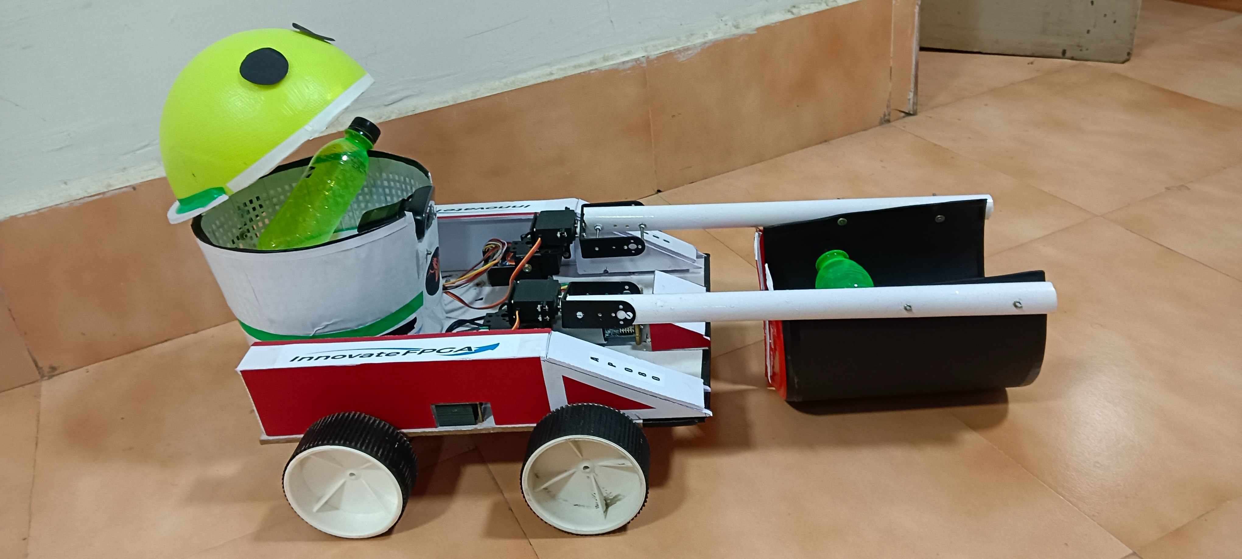
DESIGN SCHEME :
Here is the overall design view
SUSTAINABILITY RESULTS:
1. Our bot can able to pick the bottle properly without any malfunction.
2. If there are multiple bottles on a single frame, our bot cannot able to pick properly. To pick the bottle properly, only one bottle should be present inside the captured frame.
3. Our bot sends the bin status to azure cloud. So,that we can monitor the bot condition.
4. Finally our bot can be able to maneuver properly without any malfunction.
8. Conclusion
We have developed a prototype of "autonomous rag picker" using DE10 nano. It finds a very good application in development of smart cities. Our bot can able to identify and pick the bottles properly. We have also implemented a GPIO module for accessing all the GPIO pins from FPGA SoC using a customized embedded Operating System. At last, we are moving forward to test our bot on various grounds that can improve the bot's performance on several aspects to convert it into a fully customized product.
0 Comments
Please login to post a comment.