In recent years, international socioeconomic development and medical reforms have permitted the medical industry to move toward true "intelligence". The outstanding developments in medical technology have helped people overcome many challenges in life. Especially, during the global pandemic of COVID-19, besides the development of vaccines, the application of advanced technical technologies also helps people slow down the increase of the disease. The incorporation of greater artificial intelligence, internet of things in to develop robots that automatically disinfect the air and surfaces of hospital environments can help reduce the human resources spent on environmental cleaning and disinfection and minimize the risk of occupational exposure for staff. These robots also facilitate informatized management of environmental disinfection, reduce costs, and increase the efficiency of disinfection efforts.
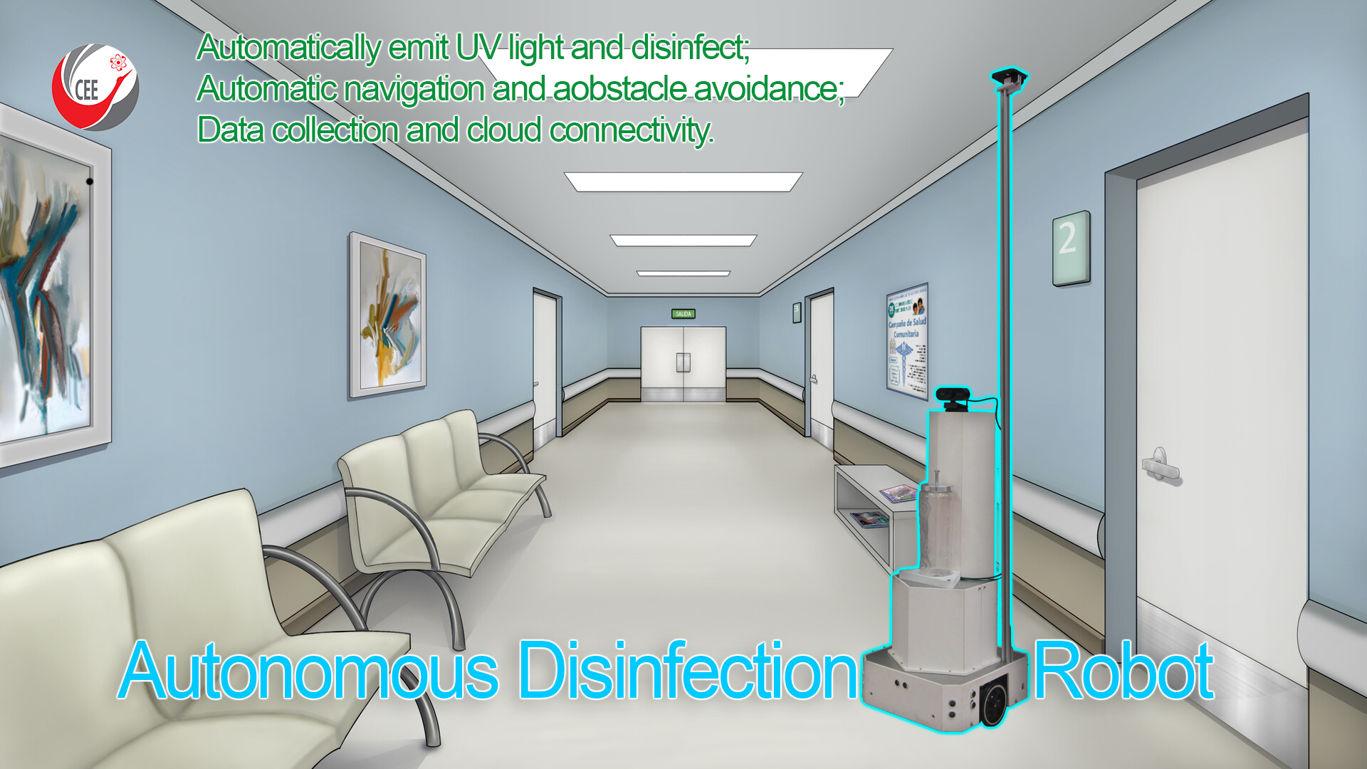
In this study, we propose to deploy a type of autonomous disinfection robot with the ability to automate tasks such as: Automatic scene recognition and disinfection; Automatic movement and avoids obstacles; Collect patient's body temperature and blood oxygen to assist in building a chart to monitor the patient's health automatically.
The autonomous disinfection robot applies AI algorithms and robotic technology to the field of hospital disinfection. In essence, the model is a disinfection robot with a high level of independent self-sensing AI. The robot model uses intelligent scene recognition, independent sensing in the disinfection process, real-time disinfection process monitoring, intelligent planning, independent execution, and evaluation of the results. An intelligent disinfection robot can compensate for the shortcomings of existing disinfection methods, improve the quality of disinfection, and reduce the probability of infection.
Demo Video
Project Proposal
1. High-level project introduction and performance expectation
Introduction
Prevention and control of hospital-acquired infections is a cornerstone of health safety and a core mission in improving the quality of health services. The combination of engineering technology and infection management in hospitals has led to breakthroughs in infection control technology. The outbreak of the coronavirus pandemic 2019 (COVID-19) that occurred in Wuhan, China, in December 2019 has become a significant public health emergency characterized by rapid transmission and wide. Many studies have shown that "contact with viruses-contaminated objects can also cause infection", this means that the environment and surfaces contaminated with the virus are an important source of infection promoting the development of the virus. spread of COVID-19 through physical contact. Therefore, environmental disinfection in healthcare facilities is important to cut transmission routes, prevent hospital-acquired infections, and control disease outbreaks.
Purpose and Application:
The application of robots to replace humans in disinfection activities brings many benefits such as: Reduce costs and minimize exposure to sources of infection for healthcare workers; Combine many sterilization options such as ultraviolet rays, chemical spray; Ensure the coverage of the areas to be cleaned, ensure that the requirements for cleanliness and disinfectant dosage and disinfection time are in accordance with the requirements; The robot can move to most areas of the clinic through the previously provided path data, and work at any time of the day and any time is activated; Collecting patient's health information (body temperature, blood oxygen), patient's test samples and other environmental parameters for monitoring and evaluation of the disease situation.
As shown in figure 1, based on the mobile robot platform in the form of a transport device equipped with an ultraviolet lamp, an ultra-dry mist hydrogen peroxide generator, and other types of sterilization modules, makes it possible for the robot to meet the requirements at the same time. Disinfection of a variety of environments in a hospital.
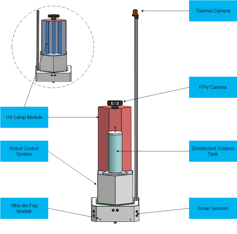
Fig. 1. Autonomous disinfection robot
The disinfection robot is developed based on an algorithmic algorithm that fusion of sensors moving in the disinfection area (Figure 2). This is a new technique in one of our studies that was published in a research paper: "Vo Chi Thanh, Nguyen Ngo Anh Quan, Tran Le Thang Dong, Tran Thuan Hoang and Minh T. Nguyen, “Fusion of Inertial and Magnetic Sensors for Autonomous Vehicle Navigation and Freight in Distinctive Environment”, International Conference on Engineering Research and Applications - ICERA 2021 (Accepted).
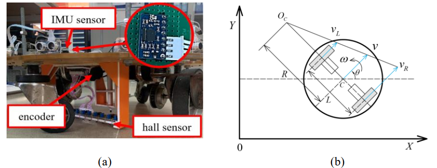
Fig. 2. (a) Action vehicle structure model; (b) Kinetic model of autonomous vehicle
Why Intel FPGAs?
One of the novelties in this project is sensor data collection and fusion will be performed using the DE10-Nano Cyclone V SoC FPGA Board. This board supports up to 40 GPIO pins, which is a good resource for connecting multiple sensors on the robot when we have to use up to 6 sonar sensors (we have to use multiple expansion boards). Using the DE-2 board can help to simplify the internal design of the robot, reduce weight and reduce the complexity of the system. With the large amount of resources on the Cyclone V chip, we plan to build soft cores that perform sensor and control processing tasks for the robot.
Why Azure IoT Hub?
The data on the scene images taken from the camera, the patient's body temperature and blood oxygen will be collected through wireless sensors and then sent to the Azure IoT Hub so that the administrator can download for monitoring and treatment purposes (Figure 3).
Targeted Users:
This application can help the following organization:
-
Hospitals;
-
Public areas exposed to the virus should be disinfected;
-
Medical institutions.
2. Block Diagram
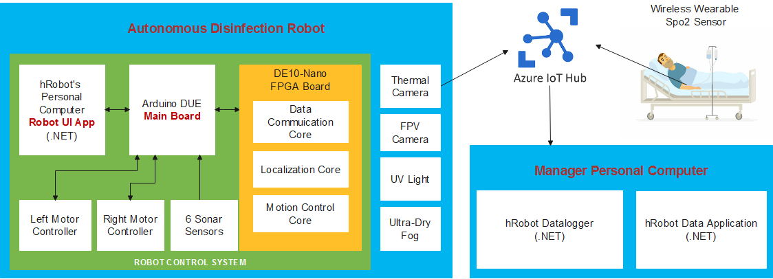 Fig. 3. Robot architecture using FPGA and Azure IoT Hub
The automatic disinfection robot system in the block diagram includes a robot control system, peripheral devices, and the Azure IoT Hub cloud system.
The robot control system consists of 3 main control blocks: the Robot Control Program (Robot UI Application) installed on the central computer, the Main Board, and the FPGA Board.
+ Main Board: The Arduino DUE Module is the central processor that will receive and synthesize the ultrasonic sensor data and the IMU sensor (on the mainboard). Then will communicate with the FPGA Board to transmit the data.
+ The FPGA Board (DE10-Nano) includes three modules: Data Communication Core, Localization Core, and Motion Control Core.
- Module Datacommunication Core is the communication block; the purpose is to transmit and receive information from the Main Board. After receiving data from the Mainboard, this block will give the data to the Localization Core module.
- Module Localization Core is the primary data processing block; the purpose is to process the robot's input and output state data according to the odometry method. The output status data of the Localization module will be transmitted to the Motion Control Core module.
- The Motion Control Core module is a control data block. The function compares the state data from the Localization Module with the Target state for processing and output control data back to the Data Communication Core module. Transmit data to the mainboard to process and send signals to control two motors for the robot to move.
Peripheral equipment blocks: including UV lights and disinfectant sprayers that are turned on by the user when the robot performs the task of disinfecting prevention; FPV camera so that the robot operator can observe the robot's movement; The thermal camera sensor will measure the patient's temperature, and the SpO2 sensor will take blood oxygen parameters and send it to the Azure IoT hub system.
The Azure IOT hub cloud system will store the patient's temperature and SpO2 data and send it to the doctor's management computer.
3. Expected sustainability results, projected resource savings
The design must be able to use the collected sensor data, synthesis of the sensor data and calculation to generate motion control signals must be must be performed on the DE10.
The design of the robot is based on the mindset of wanting to overcome the weaknesses of manual disinfection methods along with making the most of the capabilities of an autonomous machine. It is the ability to disinfect in many different ways, regulate the appropriate amount of reducing agent so as not to harm people, operate 24/7 in all hospital environments: waiting rooms, wards, operating rooms, .. .etc. Along with that is creating a solution to the urgent needs of hospitals.
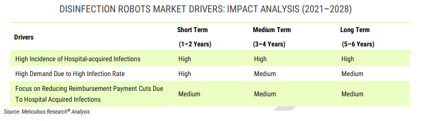
Fig. 4. Disinfection Robots Market Drivers: Impact Analysic (2021-2028)
Our robot was also created to protect one of the planet's most important resources: human resources. When human resources are improved, there will be an indirect impact on other resources. Robots can improve a medical problem just as important as covid 19: Hospital-acquired infections (HAIs). As per WHO statistics, of every 100 patients globally, seven in developed and ten in countries are at risk of developing at least one healthcare-associated infection. Further, the prevalence of HAIs is high in intensive care units (ICUs). The patients in ICUs are twice more likely to face HAIs.
According to an article published in BMC Public Health in 2021, the global prevalence of ICU-acquired infections is around 51.4%.
HAIs also exert a great economic burden on a country. For instance, in the U.S., hospitals have direct medical costs of at least.
USD 28.4 billion each year due to HAIs. Therefore, in order to reduce the prevalence of HAIs and improve patient care, there has to be thoroughness of terminal cleaning of patient rooms in healthcare facilities. Owing to the rising need to reduce HAIs, there is a rising demand for disinfection robots that can disinfect healthcare facilities efficiently. And actually, according to the analysis, the disinfection robot market is growing with an amazing CAGR: 32.84%
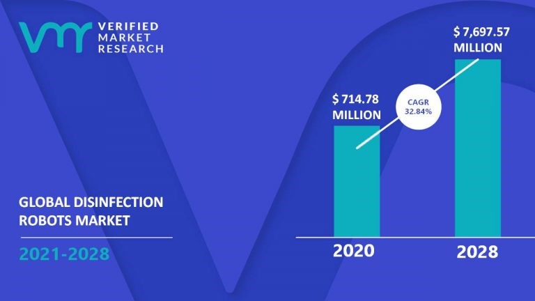
Fig. 5. Global Disinfection Robots Market
4. Design Introduction
4.1 Mechanical Design
The mechanical part is also essential in this project to ensure the robot operates smoothly and continuously throughout the working process. We use Solidworks 2021 software to design the robot's 3D drawing board. Accuracy in this stage will help speed up the manufacturing process of the actual product and save the cost of damage during trial production. In parallel with the design, the material selection stage of the parts in the robot also needs to be suitable for the environmental and machining conditions. Figure 6 shows the materials we choose to use, such as aluminium, copper, rubber wheel, Picomat...
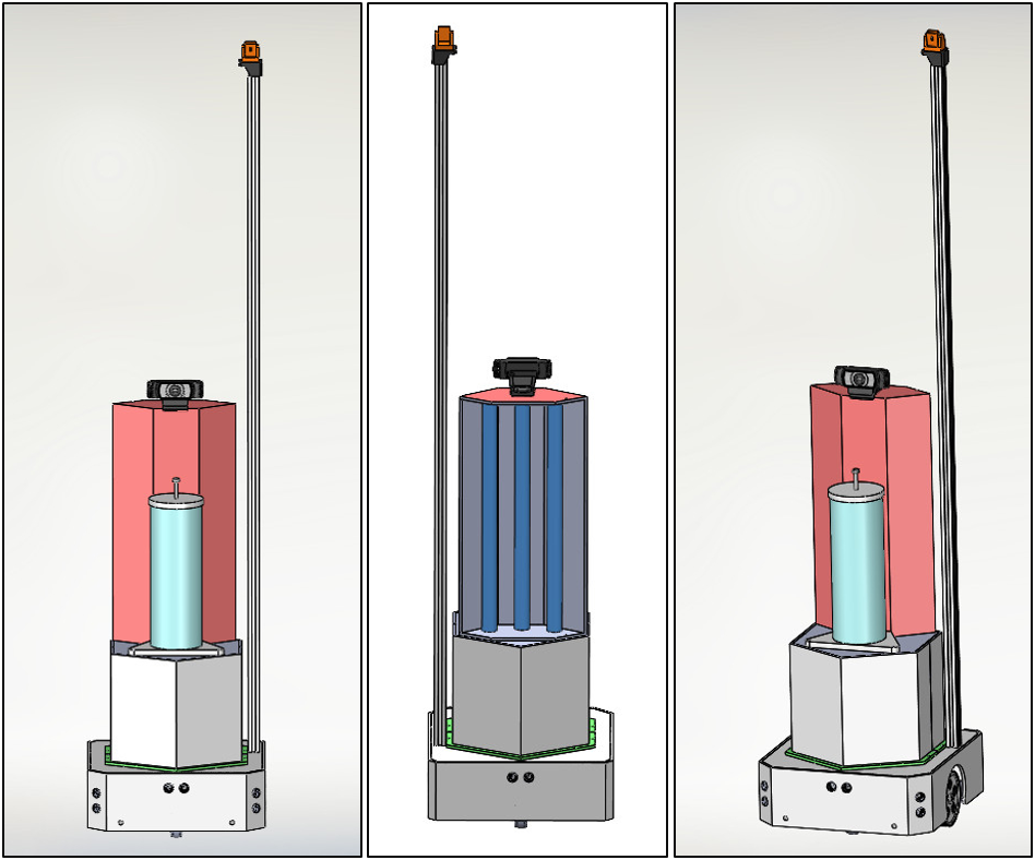
Fig. 6. Mechanical Design
Once the machine parts are fully processed, we proceed to the assembly phase and run the test of each piece to assess the reality and make necessary changes to eliminate the machine during testing process errors. Figure 7 shows us: the driven wheel structure, wheel assembly location, disinfectant solution diffusion system, system to respond to actual terrain, UV light, and control circuit system.
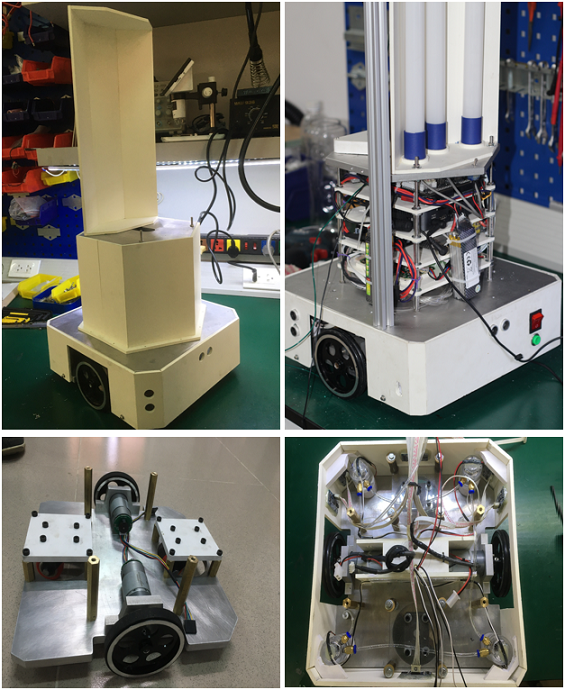
Fig. 7. Product Assembly
Finally, after testing each part, we assembled the separate parts into a unified model to complete the project. Figure 8 gives us the actual image and structure of the autonomous disinfection robot after completion.
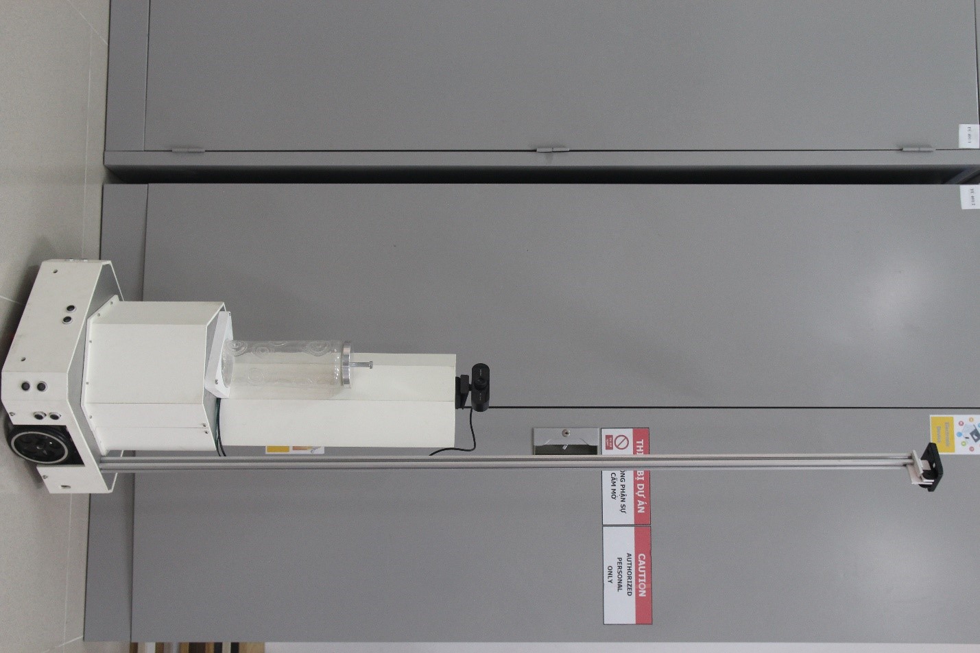
Fig. 8. Finished Product
4.2 Hardware Design
System Block Diagram
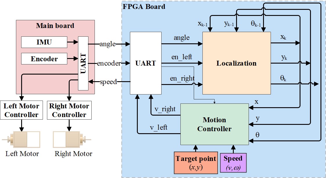
Fig. 9. Block Diagram and Signal Design
The robot's hardware consists of two circuits: the main board and the FPGA circuit. In terms of function, the main circuit uses Arduino Due as the main processor, IMU sensor is mounted on the main circuit to receive angle information. The main board communicates with the DE10-Nano FPGA board via the UART interface. As shown in figure 9, the main board sends 2 data signals, the angle and the encoder to the FPGA board. The purpose is to use the DE10-Nano FPGA board to handle localization and motion control. Because it is a UART interface, we must build the UART module from the DE10-Nano FPGA board. From the UART module receive 3 data signals as angle, left and right motor encoder. The localization module will process these inputs based on this equation of state of the odometry method. The output data will be sent to the motion control module and in addition it will be saved for processing with the next data. This is a part of localization module processing that we did on quatus software. The motion control module compares with the given data the target point and the required speed. From there output signal to the UART module to communicate with the correct speed circuit to the main board. These signals are the speeds of the left and right motors so that the robot can advance to the desired position. The main board controls 2 motors of the robot through the motor controller block.
DE10-Nano FPGA Board
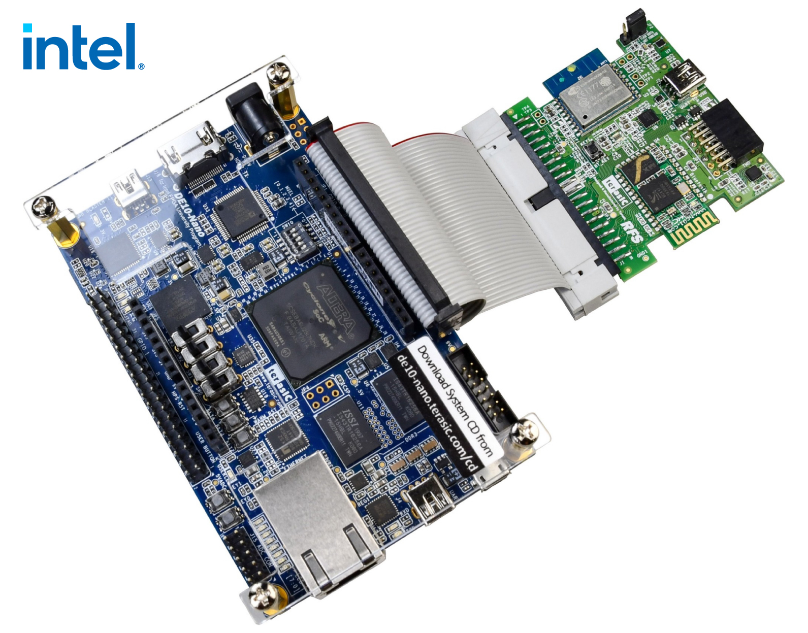
Fig. 10. Motor Driver
- DE10-Nano Cyclone V SoC FPGA Board
- Wi-Fi, using ESP-WROOM-02 module
- 9-axis sensor: accelerometer, gyroscope, magnetometer
- Ambient light sensor
- Humidity and temperature sensor
- UART to USB
- 2x6 TMD GPIO Header
DC motor control Board
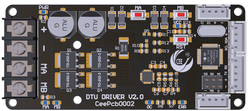 Fig. 11a. PCB 3D Design of Motor Driver
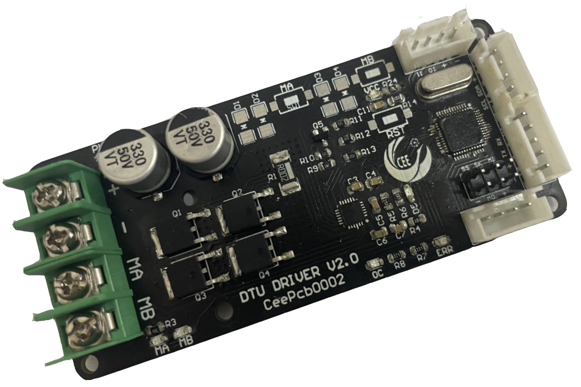
Fig. 11b. PCB Product of Motor Driver
- Bi-directional control for 1 brushed DC motor.
- Support motor voltage ranges from 6V to 30V
- Maximum current up to 13A continuous and 30A peak (10 seconds).
- 3.3V and 5V logic level input.
- Fully H-Bridge for better efficiency and no heat sink is required.
- Speed control PWM frequency up to 20KHz.
Main Board
Use Arduino Due module to read encoder data and IMU sensor data and send it to the FPGA board via UART as well as receive the speed data from the FPGA board and transmit it to the motor control board
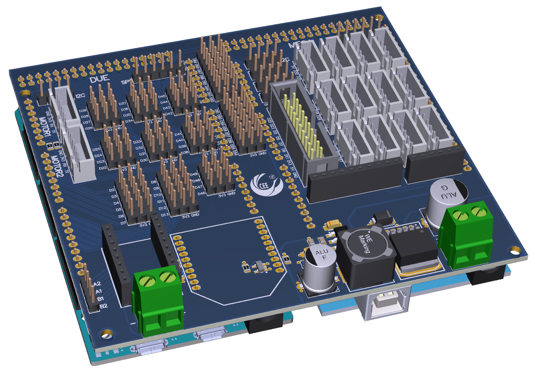 Fig. 12a. Mainboard
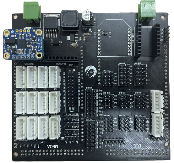
Fig. 12b. Mainboard
5. Functional description and implementation
5.1 Hardware Implementation
Locazilation
The pose of the robot is represented by a vector [x,y,θ]T where x, y are the coordinates of the robot center and θ is the angle of the robot's direction. Let the angular velocities of the right and left wheels be ωL and ωR respectively, and the sampling interval Δt is sufficiently short. So that the input control signals that are the displacement increments applied to these wheels are:
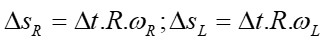
The displacement increments ΔSR and ΔSL proportional to the set speeds of the 2 wheels ωR and ωL as measured by the encoder sensors:
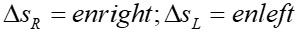
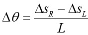
From here, the distance increment of the robot center Ds is:
And the angular increment in which the robot rotates Dθ is:
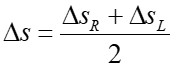
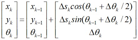
So, the equation of state of the robot at time k in the global coordinate system updated from time k–1 is as follows:
Motion Control
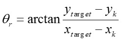
This module is used to control the robot to the target point. They combine the orientation and forward-motion control. To arrive to the target point, the robot’s orientation is controlled continuously in the direction of the target point. This direction is denoted by θr, which can be obtained easily using geometrical relations:
 |
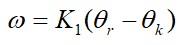
Angular velocity control ω is therefore commanded as:
Translational robot velocity is commanded as:
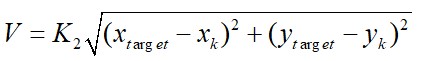
where K1, K2 is a positive controller gain.
With the distance between the two wheels L, we can calculate the translational speed of the left and right wheels as follows:
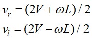
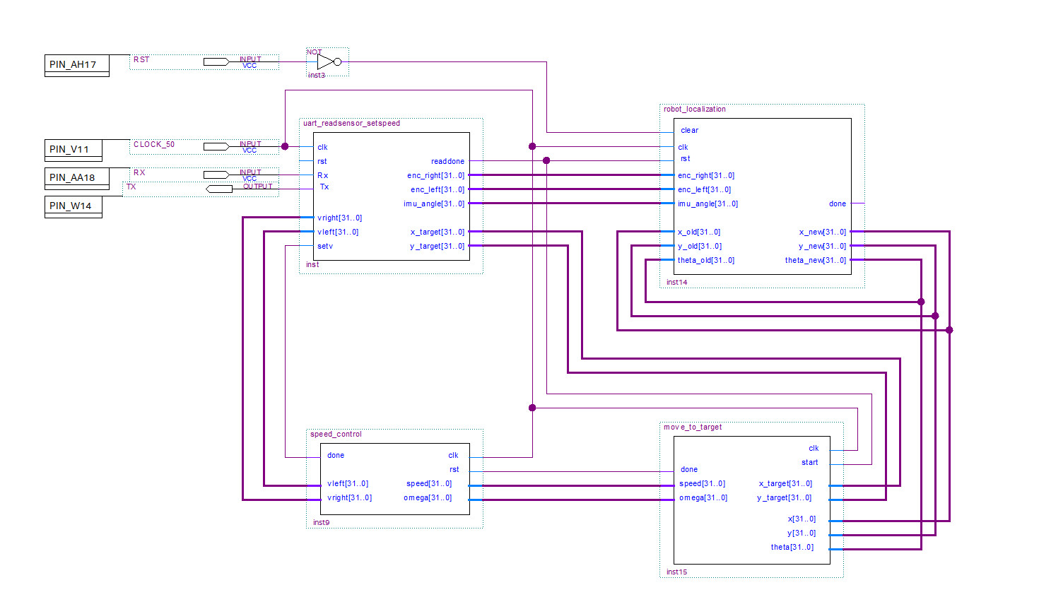
Fig. 13. RTL Design
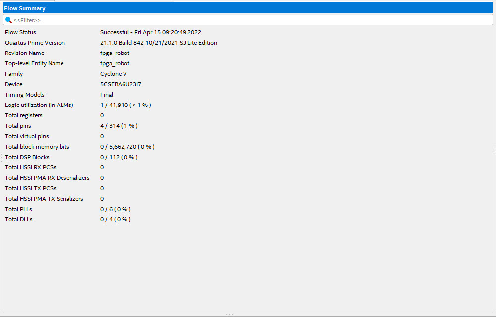
Fig. 14. Flow summary of the synthesized FPGA
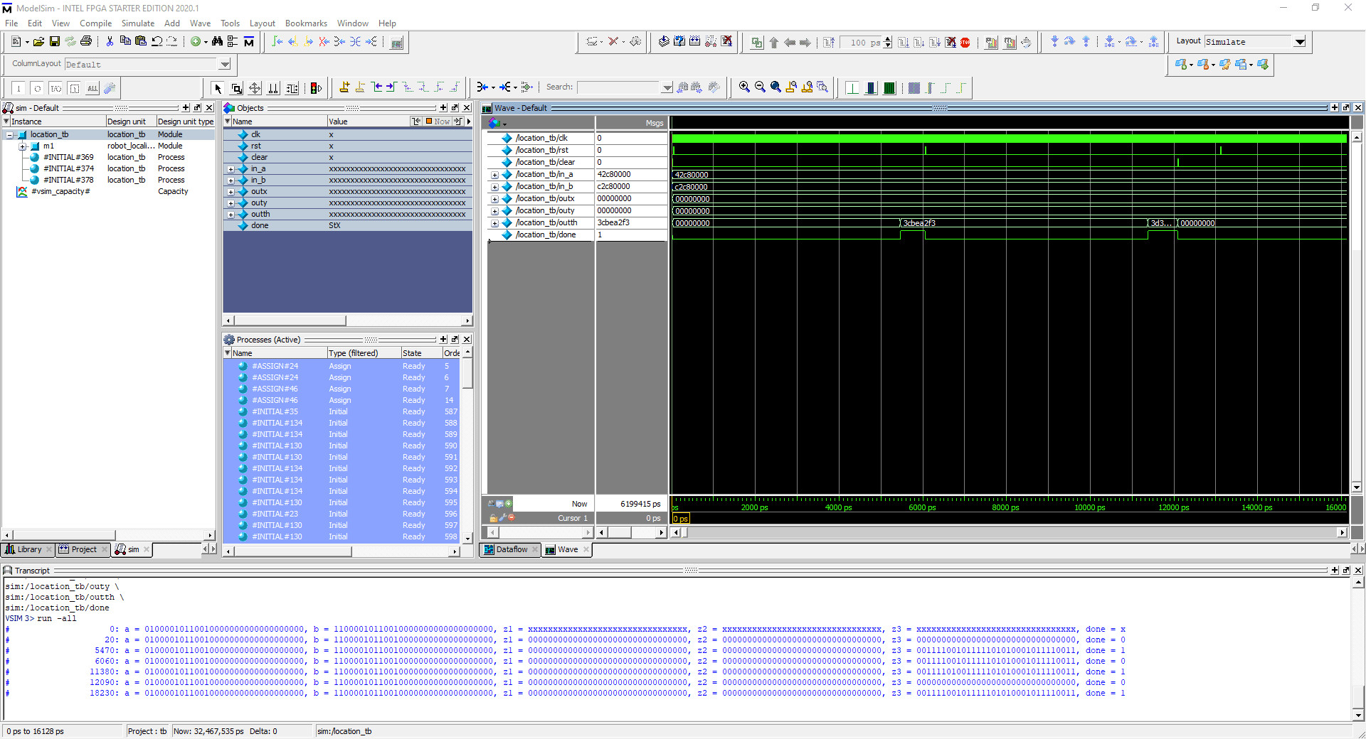 Fig. 15. ModelSim output of location core
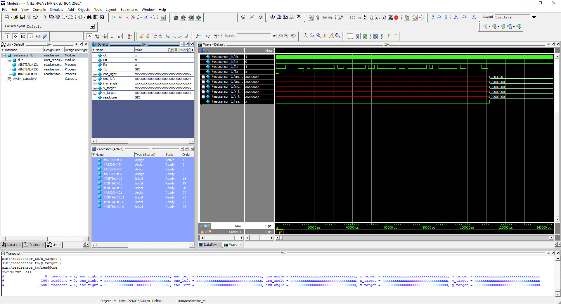
Fig. 16. ModelSim output o6f uart core
5.2 Software Implementation
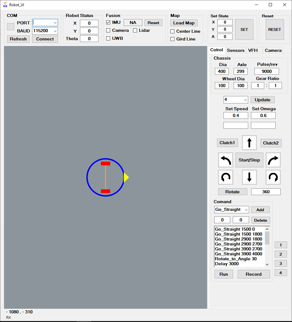
Fig. 17. Robot UI Application
The Robot UI application is installed on the computer placed on the robot, connected to the mainboard through the uart-usb port to transmit signals about the robot's moving route that has been set up previously. This data includes start position, pause points, destination, and rotation direction at each point along the way.
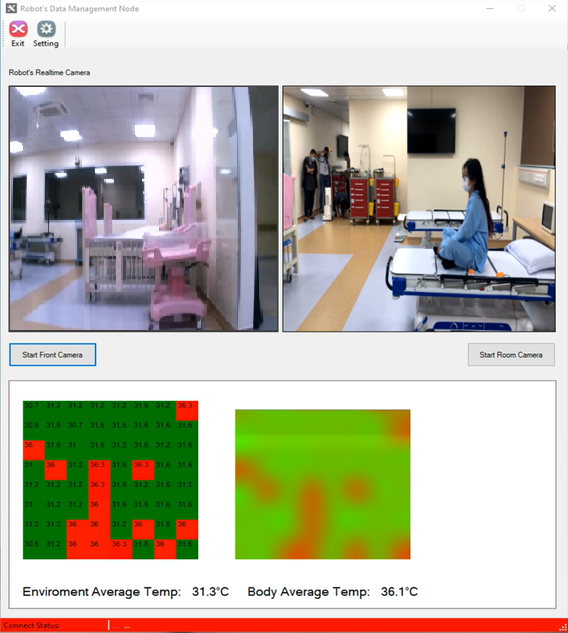
Fig. 18. Robot Datalogger Application (for Technical Manager)
The robot datalogger application is used by technicians operating robots. They can sit in the remote operating room to monitor the robot's activities, from which they can quickly identify the robot's problems to provide timely handling plans. The software displays 3 picture frames from 3 main cameras including: fpv camera, room camera, and thermal camera.
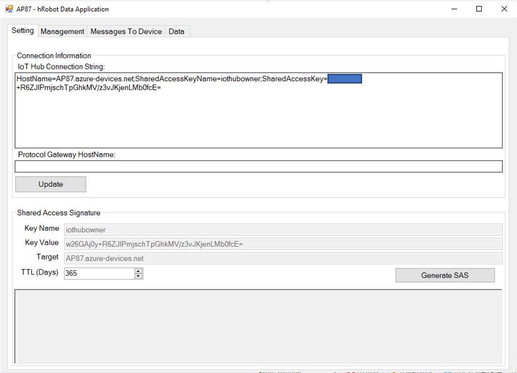
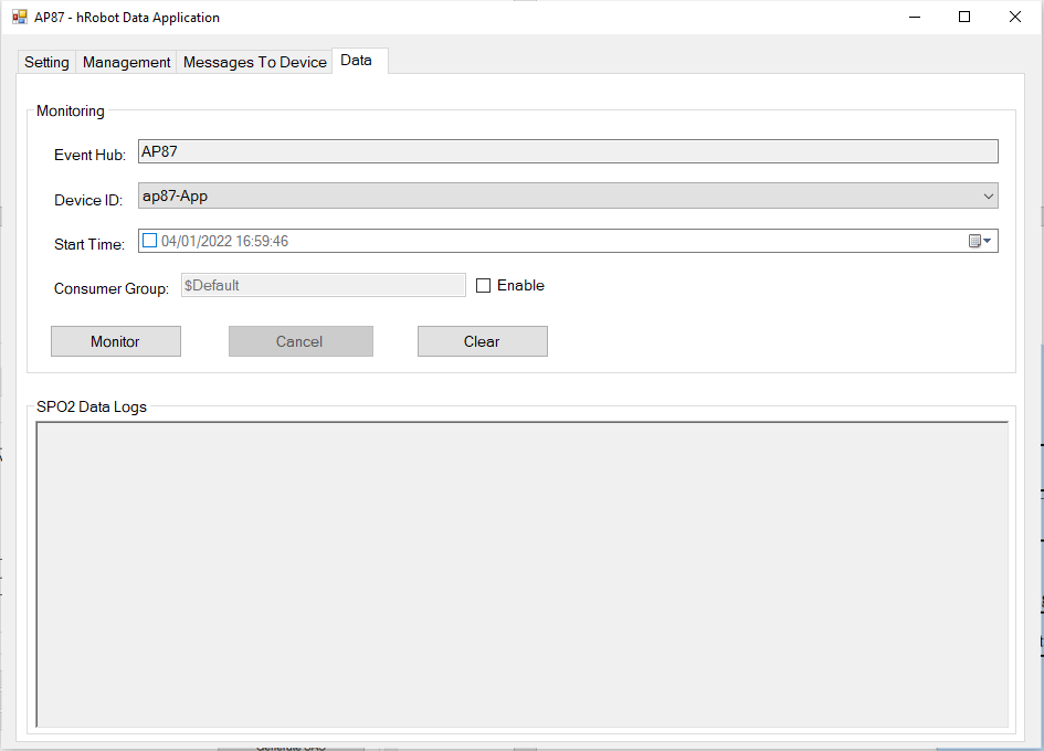
Fig. 19. Robot Data Management Application (for Doctor)
The robot data management application is installed on the medical staff's machine and connected to the Microsoft Azure IoT hub to collect patient data every time the robot enters the ward. The data is acquired using the MQTT protocol using the azure-iot-sdk-csharp library.
6. Performance metrics, performance to expectation
FPGAs are suitable for applications that are more customized and require higher processing power or speed. Accordingly, in our robot, using fpga to perform arithmetic processing blocks will give fast and accurate execution speed.
- The software on the computer is designed with a user-friendly interface, easy to use by a person without training in information technology. In short, it requires no specialized knowledge to be operated properly.
- The robot is tailored to the needs of a particular treatment room, as the system can be configured with a travel route (including distance and direction). Furthermore, other sensors can be easily included as the system's modular architecture makes it easy to remove and add hardware devices.
- It is a low-cost solution, with an estimated implementation cost of less than $1K, to be affordable even for private clinics.
From an innovation standpoint, efficiency, security, simplicity Microsoft Azure IoT Hub providing everything needed for data collection and management. In our project, it’s very easy while we just send only two types of data include body template and spo2. The data sent to the iot hub and transferred to the software on the personal computer is very fast, the speed seems to depend only on the network connection speed.
7. Sustainability results, resource savings achieved
Our robot with a compact body allows deployment in any environment from large hospitals to small clinics. It can move flexibly in many positions in the room to spray disinfectant solution and irradiate germicidal UV rays. The solution nozzles are also designed to minimize the consumption of disinfectant solutions but still ensure the distribution of the solution to all locations in the room.
FPGA is used to share a part of the mainboard's mathematical processing, this helps to increase the processing capacity of the system because it increases the parallelism in the system when the mainboard plays the role of reading the sensor. and output control commands while FPGA processes the data.
The robot can be used in a variety of medical settings and environments. Automatic movement and intelligent sterilization of multi-zones in medical facilities. The robot is equipped with several sterilization modules and automatically matches sterilization solutions to specific sterilization requirements across situations.
Task execution system based on an application that provides a travel route for the robot. The robot uses a thermal image to accurately identify the patient body temperature. These intelligent algorithms allow intelligent moving selection of disinfection solutions and enhanced disinfection capabilities (including re-sterilizing key areas and surrounding disinfection).
Disinfection information can be digitized and the sterilization work processes standardized, effectively ensuring sterilization quality. Method, location, ambient temperature and humidity, sterilization time, and cumulative use time of sterilization components and disinfectant dosage can be recorded and stored automatically.
Automatically collect the patient's body temperature and blood oxygen, and send these data to Microsoft Azure IoT Hub for treatment monitoring.
The results of this competition are part of our research project on disinfecting robots and data collection to aid treatment in high-risk infectious disease environments. Currently, we are submitting a follow-up paper of the research team on the topic of intelligent robot design to support disinfection and indirect measurement to Engineering Science and Technology, an International Journal (www.elsevier.com/ locate/jestch). The results of the article will add to the proposals to help us apply for larger research funds to realize this product to serve the community.
8. Conclusion
As mentioned in part 1, to be able to develop a self-propelled disinfection robot, we have set two main goals. Accordingly, the results are as follows:
The first goal is that the robot can move in the ward automatically thanks to the pre-established path data. The robot can avoid obstacles automatically through sonar sensors. In addition, the robot is integrated with a disinfection spray system and a germicidal UV lamp that works automatically.
The second goal is to provide an automatic body temperature, heart rate, spo2 data collection solution whereby data is transmitted from the sensor to the microsoft azure iot hub by device-to-cloud messages with a device named hRobot. This data is also transferred to the software on the computer by cloud-to-device messages.
Currently, we are continuing to update the interface for software A to monitor patient health data. Our data is not stored in a database so it has limitations in making data queries.
0 Comments
Please login to post a comment.