According to the Food and Agriculture Organization (FAO) of the United Nations, one third of the food produced is wasted and the financial costs of food waste in the world could total to USD 1 trillion each year. According to United Nations Environment Programme (UNEP), approximately 1.3 billion tonnes of food is wasted annually. Besides, Asia produces 50% of global food waste with China, Japan and South Korea alone contributed to 28% of the global disposed food. According to the Future Directions International (FDI), South and Southeast Asia on the other hand contributed to 25% of global food waste. In Malaysia, the food waste produced is 2,921,577 tonnes per year from households alone. This is equivalent to 91 kg of food waste per capita per year generated in Malaysia. This is concerning since Malaysia is the highest country to produce the amount of food waste among Southeast Asia countries.
To address the problem of excessive food waste in Malaysia, biogas could be a solution. Biogas is a renewable energy source produced by the breakdown of organic matter such as food waste to produce mainly methane and carbon dioxide gases which are environmentally friendly. Another end product which is the digestate can also be used as fertilizers since it is rich in nutrients. Globally, coal and natural gases are mainly used to generate electricity – even cooking. With the used of biogas to occasionally replace these two resources is seemed to be more sustainable since biogas is renewable energy – more resources could be saved.
In line with the aim of this year's InnovateFPGA competition, which is "Enabling the Edge for a Sustainable Future", a mini biogas plant with AI monitoring features capable of producing methane gas from food waste through Anaerobic Digestion (AD) is proposed under the food waste category to help address the problem of excessive food waste particularly in Malaysia. This mini biogas plant will be smaller compared to the other biogas powerplant in industry which means it is also portable and just can be put in the backyard. All the food waste generated daily in the household could be ‘reused’ for two main purposes: heating (for cooking) and electricity. Several key parameters are affecting the AD process: pH, temperature, C/N ratio, Volatile Fatty Acids etc. The use of FPGA in this project is to provide an Artificial Intelligence (AI) implementation to the system to optimize the biogas yield from the food waste by controlling the pH and the temperature.
Demo Video
Project Proposal
1. High-level project introduction and performance expectation
Anaerobic Digestion (AD) is a process where organic matter is degraded biologically to produce biogas. Biogas is primarily composed of methane (CH4) and carbon dioxide (CO2), with trace amounts of hydrogen sulphide (H2S), moisture, and siloxanes. There are several key parameters affecting the AD: pH, temperature, Volatile Fatty Acids, C/N ratio, organic loading rate, hydro retention time and the design of the digester. This design aims to optimize several key parameters of AD process since the slightest improvement of parameters in the process can hugely affect the amount of end products. Since the design aims to make the biogas plant to be ‘mini’ and ‘portable’, it needs to ensure that the parameters are being optimized so that even small amount of food waste can yield a great amount of biogas. Among all the aforementioned key parameters, the two most crucial are the pH and the temperature. There are three conditions where anaerobic bacteria can grow: psychrophilic (10-30°C), mesophilic (30-40°C), thermophilic (50-60°C). Several research works have shown that thermophilic condition is the most suitable for anaerobic bacteria growth since AD performances increase with temperature. For the pH, the optimal pH is between 6.8-7.4. The more AD process occurs, the more acidic it will be. The pH needs to be controlled since if the pH drop to less than 6.6, the bacteria growth will be slower and eventually leads to the failure of AD. This design will optimize these two parameters to yield a great amount of biogas with just small amount of food waste.
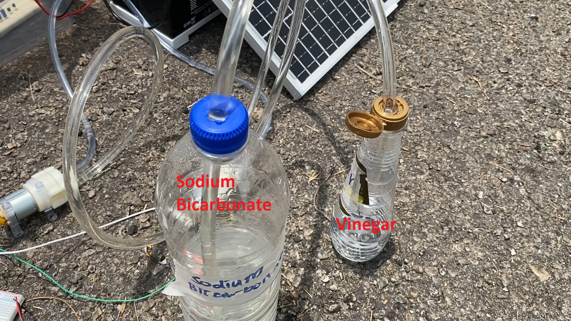
For this design, an automated supervision will be implemented using the FPGA in order to provide a suitable feedback to optimize the AD process. If the temperature is too low, the heater will heat the water to thermophilic condition. The acidity and the alkalinity during the process will be controlled using vinegar or acetic acid (CH3COOH) and baking soda or sodium bicarbonate (NaHCO3). The main reason of the use of these two solutions is mainly because both of this solution is easily available in the supermarket (since we want this biogas digester to be 'home-friendly') - so any people can add the solution if the soultions has run out. The use of Microsoft Azure IoT for data storing and monitoring will also allow the system to be controlled and supervised remotely.
The use of FPGA is just not cheaper but also could provide great performance with low latency. Besides, it is also popular for its low power consumption ability. The advantage of FPGA that could handle multiple sensors at great efficiencies at once could also be helpful in developing this design.
The targeted user will be any person or individual that wanted to get this mini biogas plant for household use to reduce the electricity consumption and eventually the monthly bills. The gas produces could also be used for cooking. Besides, this mini biogas plant will also come in handy especially when there is power outage due to some disasters or any emergencies. Apart from that, this mini biogas plant can also be used in agricultural industry since another end-products of AD process is digestate which could be used as fertilizers. The electricity generated from this plant could be used for water pump or smart farming. Since Malaysia is an agricultural country, it was estimated that 1.2 million tonnes of agricultural waste are disposed in landfills annually, and agricultural waste generation in Malaysia is at approximately 0.122 kg/cap/day in 2009 and projected to reach 0.210 kg/cap/day by 2025. Meanwhile in the United States, farm losses are likely to range 15% to 35% and the total annual losses including the retail sector and supermarket can also somehow range between 90 billion to 100 billion dollars each year. So, if all these agricultural wastes could be ‘used’ back to generate electricity, it will be really helpful in solving the excessive agricultural waste issues.
2. Block Diagram
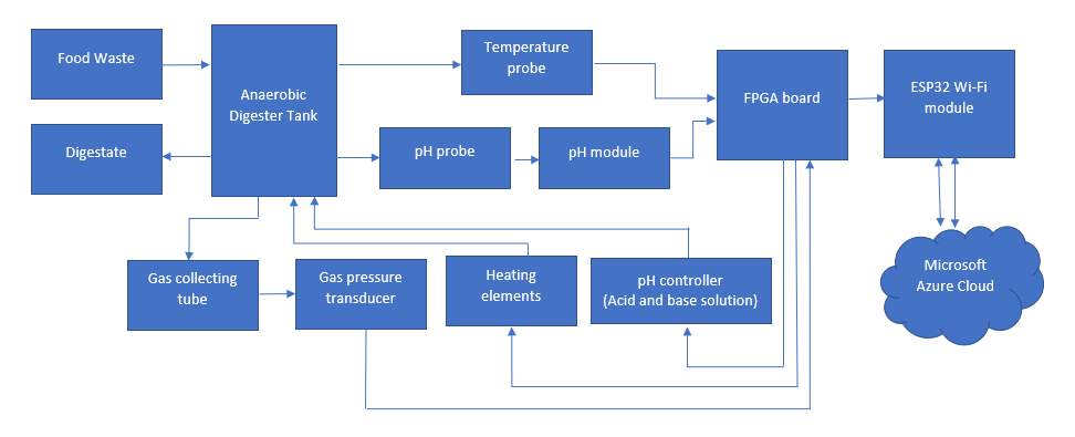
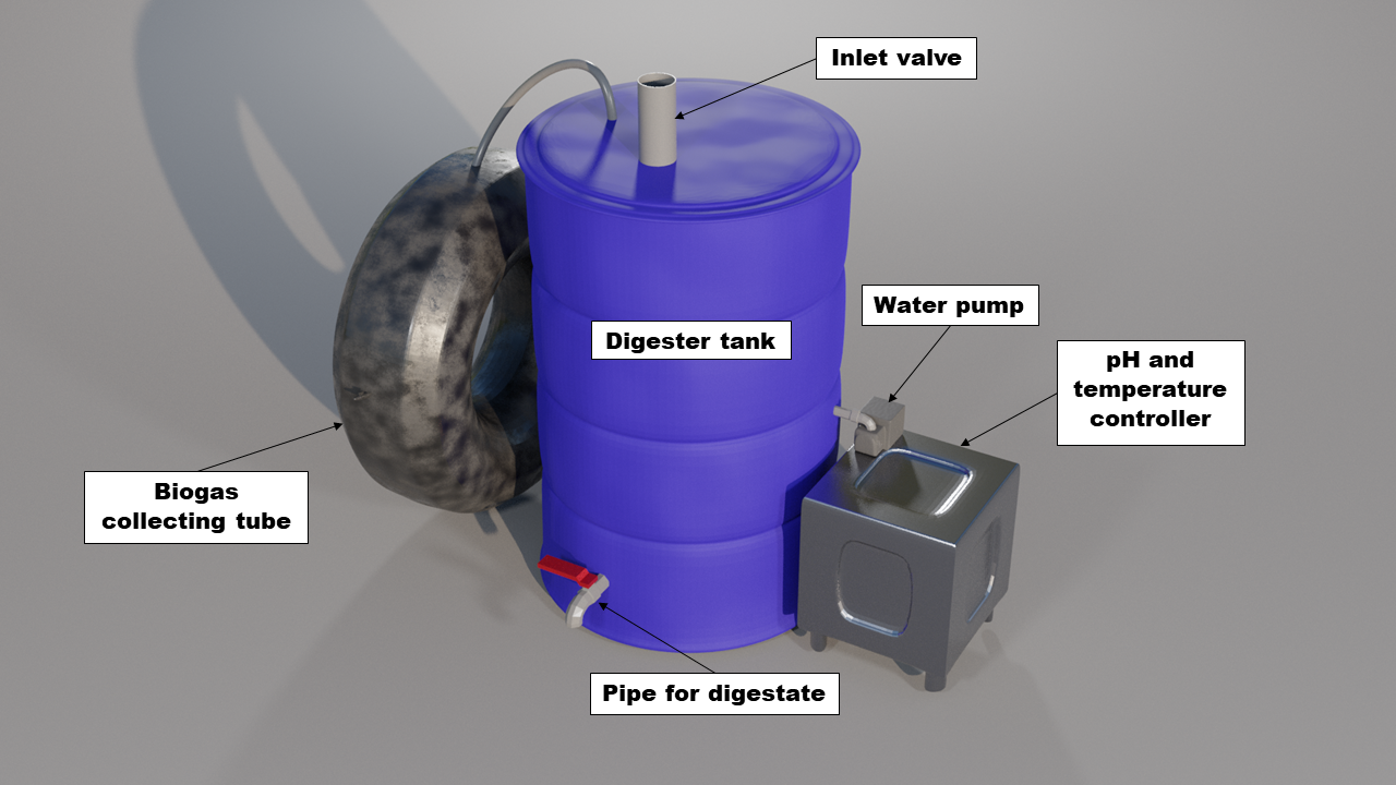
Firstly, before the food waste is being fed into the digester tank through the inlet valve, it needs to undergo the pre-treatment process (cutting the food waste into smaller pieces. This is because hydrolysis is the rate-limiting step for AD process. To enhance the hydrolysis rate, the food waste should either be ground or cut into smaller pieces. To ensure the AD process is performing properly, the digester tank should be airtight. In the digester tank, temperature probe and pH probe will be put to measure and collect real-time data. Both probes will be connected to DE10-Nano Cyclone V SoC FPGA Board. All the real-time data will be sent to FPGA for predictive analysis to provide suitable feedback for parametric optimization. The use of Microsoft Azure IoT will also allow the data to be stored and monitored in the cloud. If the temperature in the digester tank is not in the thermophilic condition, the heater will be turned on. The same is true for the pH control; the pH controller will consist of vinegar (acidic solution) and baking soda (sodium bicarbonate). The solution will be pumped into the digester tank accordingly – to ensure that the pH is in favourable condition. The biogas that was produced will be channelled to the gas collecting tube. Gas pressure transducer sensor will be used to measure the gas pressure and the data will be sent to the FPGA to be analysed.
3. Expected sustainability results, projected resource savings
The performance of this project will be measured using three parameters:
Food waste reduction:
Food waste is a serious global issue. It was estimated almost half of the food produced actually turned into waste. The food waste will eventually end up in landfills. According to the study conducted by the National Solid Waste Management Malaysia (JPSPN), food waste took up about 31% to 45% of the total volume waste generated daily in Malaysia. By using this mini biogas plant, it is expected that at least 60% of food waste from household could be used to feed the digester tank. The same goes for agricultural industry; once the cropping season starts, the farmers usually face similar problems each year where the supply is high, but the demand is relatively low. So, the agricultural waste could be fed into the digester tank for better utilization.
Volume of biogas yield:
According to research conducted by Technical University of Kenya, if there was enough waste, 24 m3 of biogas could be produced from 100kg of kitchen waste (Ogur & Mbatia, 2013). However, with parametric optimization, the amount of biogas yield is predicted to be higher than this value.
Electricity production:
Biogas provides a better and clean energy to the environment. With the use of biogas to occasionally replace the use of normal electricity generated from power plants, it is estimated that the user could save a lot of money just from the electricity bills. Taking the estimation value from the previous references, if 100 kg of food waste could produce 24 m3 of biogas at a minimum, 1 kg of food waste is estimated to be able to produce around 0.24 m3 of biogas (note that this is just an assumption since the amount of biogas yield also depends on the AD performances, digester tank, as well as the weight of the food waste). According to Association Québécoise De La Production D'énergie Renouvelable (AQPER), each cubic meter of biogas could produce about 2kWh of electricity – which could light a 100W bulb for 20 hours and run 2000W of hairdryer for an hour. According to UNEP report published in 2021, average Malaysians produced about 91 kg of food waste per capita for household. Assuming that only 60% of the food waste is being used to feed the mini biogas plant, the amount of food waste that gets into the digestor tank will probably be around 54.6 kg – which means that the amount of methane gas that is able to be produced is about 13.104 m3. Thus, the electricity that could be produced is estimated to be around 26.208 kWh.
Cooking gas:
The use of the biogas for cooking also could save some money for the users from buying the Liquefied Natural Gas (LNG) – that is commonly used in the kitchen nowadays. This could be better since LNG is non-renewable energy while biogas is renewable energy.
4. Design Introduction
The Mini Biogas Plant was implemented using DE-10 Nano with the help of ESP32 for communicating with Microsoft Azure through Wi-Fi. The DE-10 Nano was used to control the temperature and pH of the tank to optimize the biogas production. FPGA is a good platform for a mini biogas plant due to the scalability of designing a system using an FPGA. By using an FPGA, the designer can choose to implement how many peripherals can be connected to the FPGA. This can help to minimize the cost to implement the system if the multiple tanks need to be added since all tanks can be connected to a single FPGA board.
The purpose of the design is to produce an affordable and reliable mini biogas plant with minimal maintenance needed. This will help to increase the adoption rate of biogas system used by end user which can help to reduce the use of non-renewable energy.
This biogas plant is targeted to liquefied petroleum gas users. This system was aimed to reduce the use of the use non-renewable liquefied petroleum gas and preserve it for more crucial use cases.
5. Functional description and implementation
The design of the system consists of two processes which are the process for controlling the parameters in the biogas tank and data collection process for data monitoring through Microsoft Azure Cloud. The system was powered by lead-acid battery which was connected to a pair of solar panels.
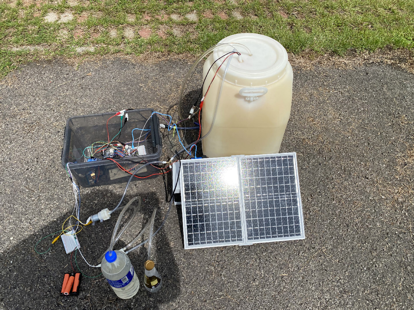
Prototype diagram
Biogas Parameters Controller
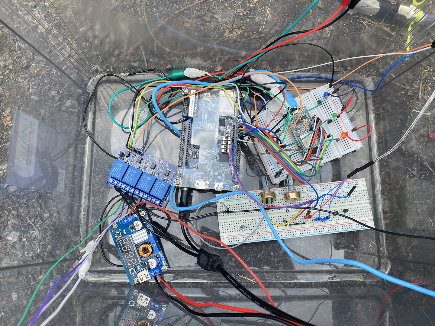
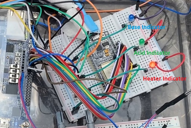
The controller system utilizes a Nios II embedded processor architecture which was programmed into the DE-10 Nano. The use of Nios II architecture allowed us to implement custom peripherals for reading the pH sensor, temperature sensor and pressure sensor and controlling the heater and water pumps.
The built-in LTC2308 ADC was used to obtain all data from the sensors. The ADC uses SPI protocol to communicate with the FPGA. The ADC Controller for DE-series Boards which is available in the University Program library with only 3 channels was configured in the Platform Designer. Furthermore, several PIO ports were also configured for the heater, pumps and for communicating with the ESP32 for data monitoring.
C program was written for the Nios II to communicate with the peripherals connected to the FPGA. The desired maximum, minimum and target values for the pH and temperature of the tank was set in the C program. The desired valued was obtained after the sensors were calibrated. Apart from that, several functions were written as shown below.

The compiled SOF from the hardware implementation and the ELF file generated from the C program was combined into one JIC file to be stored on the EPCS device on the DE-10 Nano.
Data Monitoring Through Microsoft Azure Cloud
ESP32 was used by the system to communicate with the Microsoft Azure Cloud through Wi-Fi. ESP32 receives data from DE-10 Nano through the PIO ports as configured in the Platform Designer. The received data were then converted into a readable data before sending it to the Microsoft Azure.
6. Performance metrics, performance to expectation
The design needs to make sure that the pH value of the tank stays between 6.8 and 7.4. The pH value should not fall below 6.4. The pump function in the C program was written to control the pH value. In the function, the sodium bicarbonate pump started to turn on when the pH level falls below the stated minimum pH, which was 6.8. the function will trigger the pump to turn on every time it is being called until when the pH exceeds the target pH, which was 7.1. When this happens, all pumps will be turned off and the function will only turn one of the pumps on if the pH level is outside of between 6.8 and 7.4. If pH level exceeds 7.4, the vinegar pump will be triggered. The function will continue triggering the pump when it is called until the pH level drop below 7.1. If a pump was triggered, it only be turned on for 4 seconds, then waits for 20 seconds for pH in the tank to normalize before taking another pH reading.
The temperature of the tank needs to be within the thermophilic region which is between 50℃ and 60℃. The heat function in the C program was written to maintain the temperature. When the temperature falls below 50℃, the heater will be turned on. The heater will be turned off when the temperature exceeds 60℃.
The gas pressure in the parametric optimized tank should be higher than the control tank.
The processing speed of Intel FPGA is adequate to maintain within the desired range.
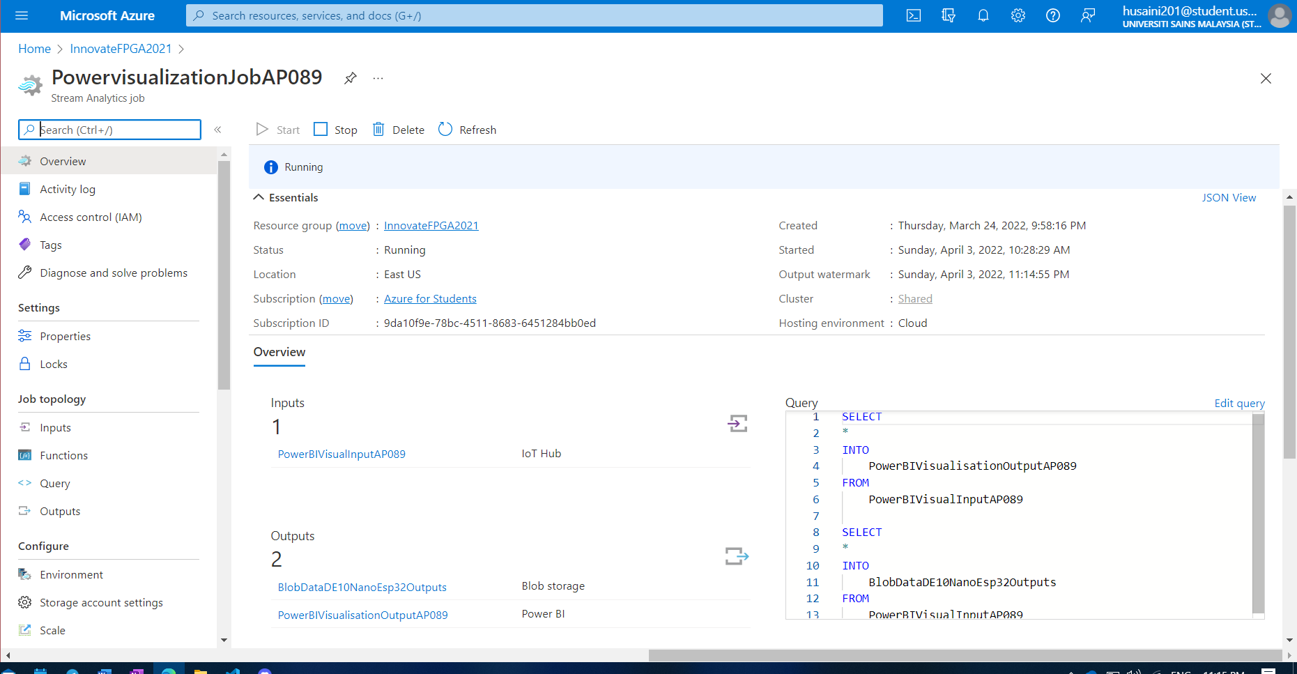
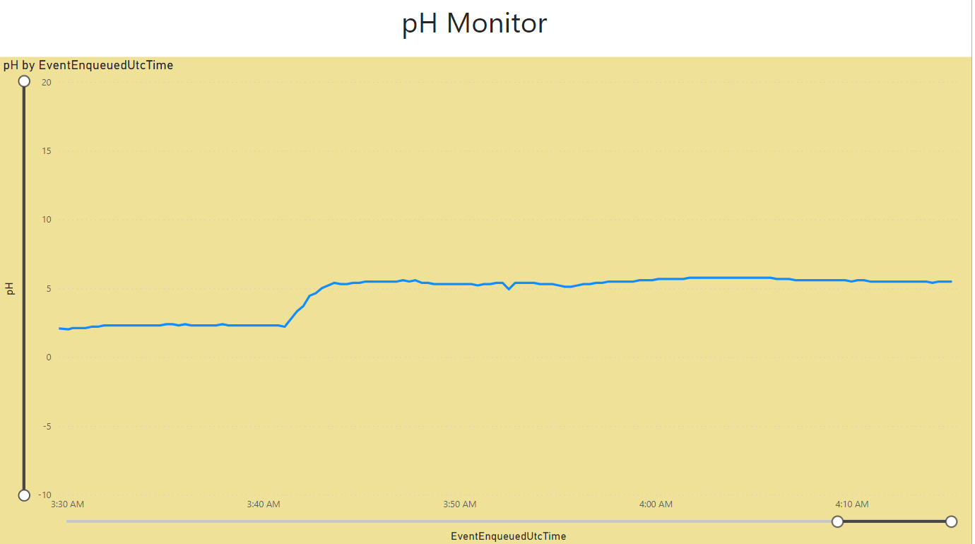
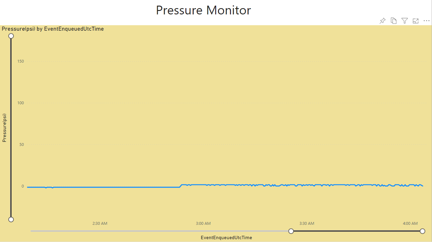
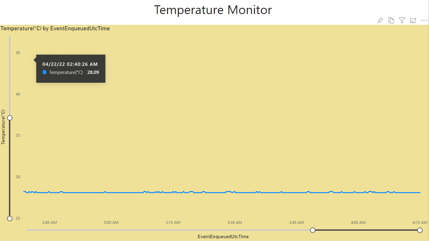
The data obtained by DE-10 Nano were transfered to the ESP32 before sending in to PowerBI which is powered by Azure.
7. Sustainability results, resource savings achieved
System Design Scheme

Hardware Design Block Diagram

Software Flow
C program for Nios II soft processor was used to control the peripherals connected to the FPGA. First, the optimal parameters such as desired pH values and temperature values were assigned to the variables. Then, the data from pH, temperature and pressure sensors were read from the ADC. Then, the obtained values were converted and stored in the variables. Next, the data was sent to the ESP32 to be uploaded to Azure. After that, the obtained pH value was evaluated to control the pump as explained in the previous section. Then, some delays were added to give some time for the pump to pump the liquid before stopping it. After that, the temperature was evaluated to control the heater as explained in the previous section. The system paused for 20 second before restarting the process.
8. Conclusion
The system did works as it should which is according to the values of the sensors obtained from the DE-10 Nano’s built-in ADC. However, the detected values sometimes fluctuated from the correct value. We were suspecting that the electrical connection between the sensors and the ADC were not in the optimal condition due to the use of breadboard making the connection loose. We could have soldered all sensors pins to ensure a proper connection. Furthermore, we have substituted the artificial intelligence aspect of the system with a known good parameter due to time constrain and we still need to improve our understanding regarding it to create a reliable and functioning model.
Apart from that, throughout the development of the system, we have learnt a lot about the many ways to develop using Intel FPGA platform. In was an eye-opening experience for us, undergraduate students to be able to utilize the knowledge that we have learnt in the university.
0 Comments
Please login to post a comment.