
Our project is a smart system to track traffic in city streets to track traffic densities, and it can also detect driving violations.
Demo Video
Project Proposal
1. High-level project introduction and performance expectation
Nowadays, development is synonymous with construction of infrastructure. Such road infrastructure needs constant attention in terms of traffic monitoring as even a single disaster on a major artery will disrupt the way of life. Humans cannot be expected to monitor these massive infrastructures over 24/7 and computer vision is increasingly being used to develop automated strategies to notify the human observers of any impending slowdowns and traffic bottlenecks. However, due to extreme costs associated with the current state of the art computer vision based networked monitoring systems, innovative computer vision based systems can be developed which are standalone and efficient in analyzing the traffic flow and tracking vehicles for speed detection. In this article, a traffic monitoring system is suggested that counts vehicles and tracks their speeds in realtime for multi-track freeways . Proposed algorithm uses Gaussian mixture model for detection of foreground and is capable of tracking the vehicle trajectory and extracts the useful traffic information for vehicle counting. This stationary surveillance system uses a fixed position overhead camera to monitor traffic and RFID Readers to record cars ID.
2. Block Diagram
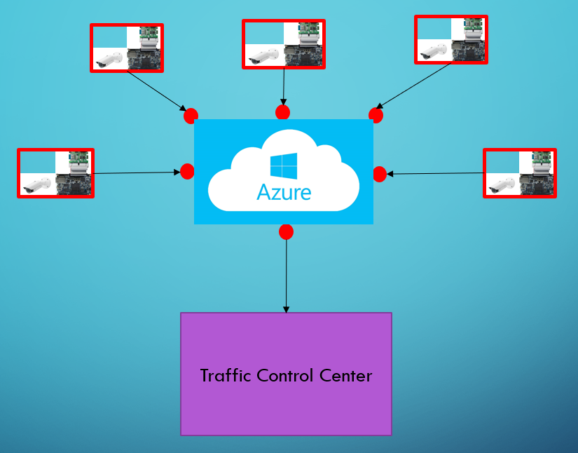
System Flow Diagram
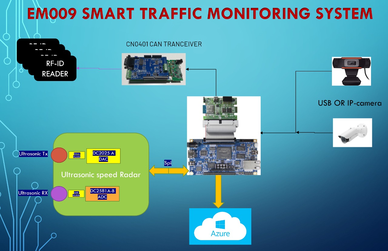
Fig 1 : General system Block Diagram
.jpeg)
Fig 2 : FPGA RTL DESIGN
3. Expected sustainability results, projected resource savings
-Multiple-vehicle detection and tracking (MVDT).
-Analyzing the traffic flow.
- Track traffic densities.
- Tracking vehicles for speed detection.
- Count vehicles.
- Automatically classify vehicles as motorcycle, passenger vehicle, truck and large truck.
-Record Cars id using multiple RFID readers connected With canbus.
- Innovative computer vision based systems can monitor traffic over 24/7 which save human resources.
- Emergencies Detection And Alerting.
-Works as weather station using RFS Sensor.
4. Design Introduction
This project is Implemented on Intel FPGA DE10 nano ,and is used for Realtime Continuous Traffic monitoring ,depending on a computer vision system And Doppler RADAR For speed detection The system connected to microsoft Azure cloud.
Our system is composed of 4 major parts
1- Car detection and clasification using computer vision (HPS Portion)
2- Doppler Radar for speed car detection (FPGA)
3- Car RFID Reader (FPGA ,Soft Core processor NIOS II)
4 -Wheather station ((FPGA ,Soft Core processor NIOS II)
5. Functional description and implementation
1-Car Detection, Classification&Counting Using OPENCV LIBRARY
In this subsystem we build an advanced vehicle detection and classification project using OpenCV. We’ll use the YOLOv3 model with OpenCV-python. Open-CV is a real-time computer vision library of Python. We can use YOLO directly with OpenCV.
We can detect heavy vehicle and light vehicle using opencv which installed in the de10 nano kit
To do this project we need :
1- De10 nano Fpga cloud Connectivity Kit ,with lxde Image(should put a cooling fan above the fpga to get the best performance from the arm soc and prevent it from speed throttling ).
2-Python 3.5
3-Opencv 4.5
4-Numpy 1.1
5-Pip 1.1
6-Yolo v 3 with pretrained model
Yolo is a real-time object recognition algorithm. It can classify and localize multiple objects in a single frame. YOLO is a very fast and accurate algorithm for its simpler network architecture
.jpeg)
Fig 3 :YOLO architecture
The YOLO network has 24 convolutional layers followed by 2 fully connected layers. The convolutional layers are pre-trained on the ImageNet classification task at half the resolution (224 × 224 input image) and then double the resolution for detection.
The layers Alternating 1 × 1 reduction layer and 3×3 convolutional layer to reduce the feature space from preceding layers.
The last 4 layers are added to train the network for object detection.
The last layer predicts the object class probability and the bounding box probability.
We’ll use OpenCV’s DNN module to work with YOLO directly. DNN means Deep Neural Network. OpenCV has a built-in function to perform DNN algorithms.
We can do the target of this project in the following steps
1. Import necessary packages and Initialize the network.
2. Read frames from a USB,IP Camera OR video file.
3. Pre-process the frame and run the detection.
4. Post-process the output data.
5. Track and count all vehicles on the road
6. Save the final data to a CSV file.
Fig show the counting and car classification
.jpeg)
Fig 4 : vehicles classification and Counting
Fig 5 : vehicles classification and Counting
.jpeg)
Fig 6 : vehicle Detection Program Running On De10 nano
Fig 7 : DE10 Nano Processor Recources Usage
* Future work can use OCR (Opitcal Character Recognition) to identify vehicle plate no ,inorder to get accurate data for the vehicle Traffic Violation ,or Accident.
2- Ultrasonic Doppler Radar
An ultrasonic Doppler radar is designed and implemented to obtain the velocity of vehicles.
Introduction
The objective of this subsystem is to develop an accurate ground speed sensor for vehicles.
- Prototype sensors were made and tested.
.jpeg)
Fig 8 : Ultrasonic Doppler Radar Block Diagram
Fpga Schematic Block diagram
.jpeg)
Fig 9 : Fpga Schematic Block diagram
The radar consists of ultrasonic transducers of 40 kHz ,Use De10 nano Kit for signal synthesis and Digital signal processing.
The 40 khz is calculated using matlab , with sampling frequency of 600khz ,then for every sine we have 15 sample which is stored in LUT in the FPGA .
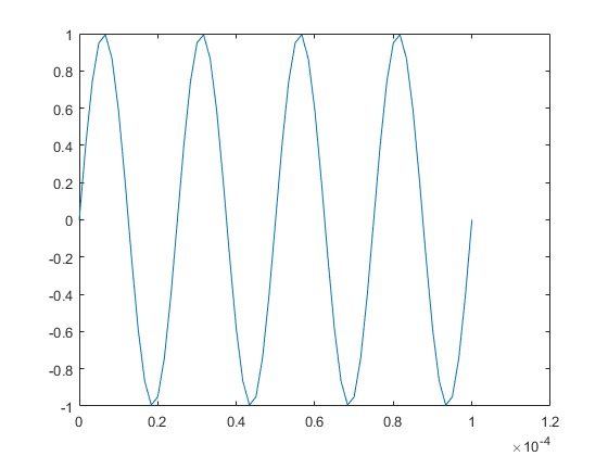
.jpeg)
Fig 10,11 TX signal simulation using matlab and synthesis data samples using FPGA
Dac Evaluation Kit DC 2025A Is interface with FPGA using spi protocol at speed clock of 20 Mhz ,the 15 samples are feed to the Dac to generate the 40 khz from ch0 with voltage swing from 0 to 5 volt .
.jpeg)
Fig 12 : TX Signal Generation using De10 nano and DAC DC 2025A .jpeg)
Fig13 Tx signal generation
Then 40khz is feed to the tx ultrasonic transcducer through driver ,also the received echo is amplified after received from th ultrasonic RX sensor .
.jpeg)
Fig14: Ultrasonic Transmitter& Receiver ,Driver Circuit Fig15 :Ultrasonic Transmitter& Receiver
Then The amplified received echo feed to the ADC KIT DC2581A-B at ch1 , ADC is interfaced with FPGA through SPI.
The main Idea is to extract Doppler frequency from the received echo , The sonic wave is reflected diffusely on the ground where it is separated into many weak sounds, a few of which are received by a receiver. The Doppler effect causes the frequency to be shifted. If FD denotes the Doppler shift, the frequency of the received signal is F0+FD. The signal is amplified and mixed with the transmission signal in a mixer to create the beat-frequency signals.
The lower frequency beat is filtered through a low-pass filter and is the sensor output. Therefore, the output frequency FOUT is equal to the absolute value of Doppler shift |FD|.
On the assumption that air is stationary relative to the ground, the Doppler shift FD is given
by:
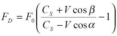 (1)
(1)
Fig16 :Doppler Frequency Equation
where CS is the velocity of sound in air, V is the vehicle velocity relative to the ground, α is the angle between the vehicle velocity vector and the transmitted direction of the ultrasonic wave, and β is the supplement of the angle between the vehicle velocity and the direction of the received wave.
The output frequency is approximately proportional to the transmission frequency and the absolute value of CAR velocity(Which we can calculated from the equation).
Fig17 :Transmitted signal (in yellow ) & received Echo (BLUE)
Fig18 :A complete setup for the Doppler Radar
3- CAR RFID Reader:
In this subsystem we can read the ID of any passing car using RFID _Node ,our system can integrate any no of nodes connected through can bus.
The advantage of can bus is to provide high speed data rate , Supports auto retransmission for attribution lost message,
.jpeg)
Fig19 :CAR RFID Reader Block Diagram
Each node contain RFID READER ,Controller(in our case Arduino Uno), Can bus tranciver Analog Devices EVAL ADM3055E-ARDZ cn041 which has can controller and can tranciever in the same module
All connected Nodes can send CAR RFID data to the master controller (DE10NANO)
.jpeg) Fig 20 : Rfid Master
Fig 20 : Rfid Master
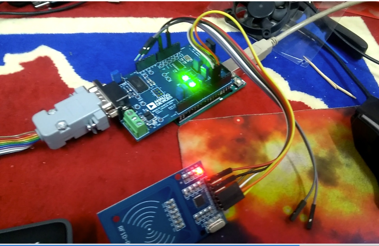 Fig21: RFID Node
.jpeg)
Fig22: showing CAR RFID Reading
4- weather station
As a complete system we also integrate a function of whether station by using RFS daughter board with de10nano connectivity kit .
A nios II soft core processor is involved to do the job,Temperature ,humidity , light sensor reading are send from RFS board to nios II, which can be send to Azure.
.jpeg)
Fig 23: Readings From the wheather station
6. Performance metrics, performance to expectation
In this section, we will go over the different performance parameters and metrics used in our Smart Traffic Monitoring System . The FPGA has been configured to interface with all sensors and evaluation modules described in the previous section .
Fig24: RTL DESIGN OF FPGA including ARM , NIOSII and Programmable Logic
.jpeg)
Fig25: RTL for Radar Logic
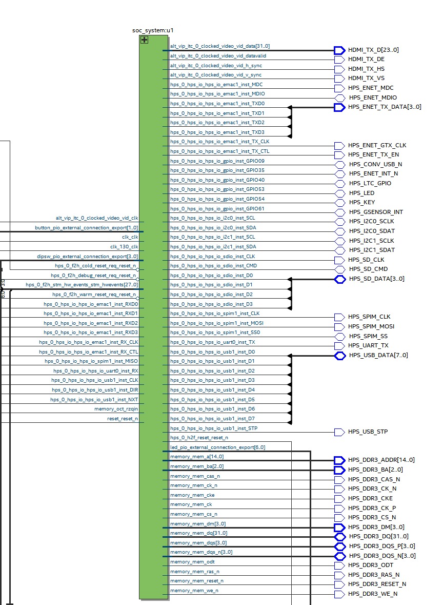
Fig 26:RTL For ARM SOC
.jpeg)
Fig 27:RTL FOR NIOSII weather station and can bus reader
in this project we utilized FPGA resources, we have employed almost all the elements available in the SoC:
1- memory blocks;
2- DSP blocks;
3 - PLL;
4 - HPS;
5 - DDR controller;
6 - ethernet controller.
.jpeg)
Fig 28: FPGA Resources Used in the Project
which integrates computer vision in De10 nano arm cpu , Doppler speed Radar in FPGA Programable logic also wheather station and Rf reader in Nios II.
7. Sustainability results, resource savings achieved
The uniqueness of the project implementation is in the next:
Nowadays a lot of devices are programmed to achieve a smart traffic monitoring system , implemented Ultrasonic Doppler Radar for speed detection,
Fig29: Tx signal generation
.jpeg)
Fig30 :BuiltIn Ultrasonic Transmitter& Receiver
.jpeg)
Fig31 :A complete setup for the Doppler Radar
.jpeg)
Fig32 :Transmitted signal (in yellow ) & received Echo (BLUE)
- A Car Detection, Classification&Counting Using OPENCV LIBRARY and Yolo We can detect heavy vehicle and light vehicle using opencv which installed in the de10 nano kit.
.jpeg)
Fig33 : Car Detection and classification
.jpeg)
Fig34:Classified Vehicles Counting
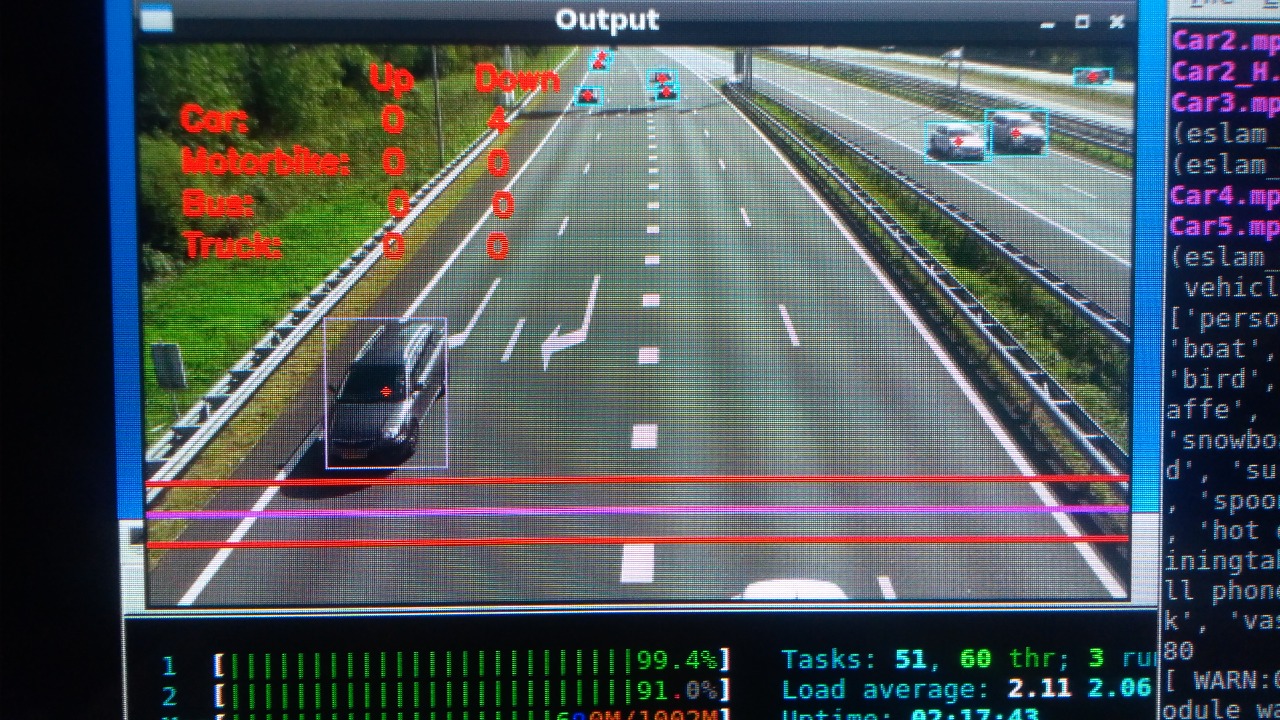
Fig35 :Multiple Vehicle Detection And classification
.jpeg)
Fig36 :ARM Processor CPU And Ram Utilization
We used OpenCV’s DNN module to work with YOLO directly. DNN means Deep Neural Network. OpenCV has a built-in function to perform DNN algorithms.
Yolo is a real-time object recognition algorithm. It can classify and localize multiple objects in a single frame. YOLO is a very fast and accurate algorithm for its simpler network architecture.
- by Using RFID reader Nodes And Master connected with can bus which provide high speed data rate , Supports auto retransmission for attribution lost message, we are able to read Vehicle ID when passed Under the Node .

Fig37: RFID Node
.jpeg)
Fig 38 : RFID Master
Collecting these Id using master controller and send it cloud service microsoft azure
.jpeg)
Fig 39 : RFID Master
As a complete system we also integrate a function of whether station by using RFS daughter board with de10nano connectivity kit .
A nios II soft core processor is involved to do the job,Temperature ,humidity , light sensor reading are send from RFS board to nios II, which can be send to Azure.
.jpeg)
Fig 40 : CAR RFID Reading
Smart Traffic monitoring is Strongly needed ,as even a single disaster on a major artery will disrupt the way of life , Humans cannot be expected to monitor these massive infrastructures over 24/7 and computer vision is increasingly being used to develop automated strategies to notify the human observers of any impending slowdowns and traffic bottlenecks.
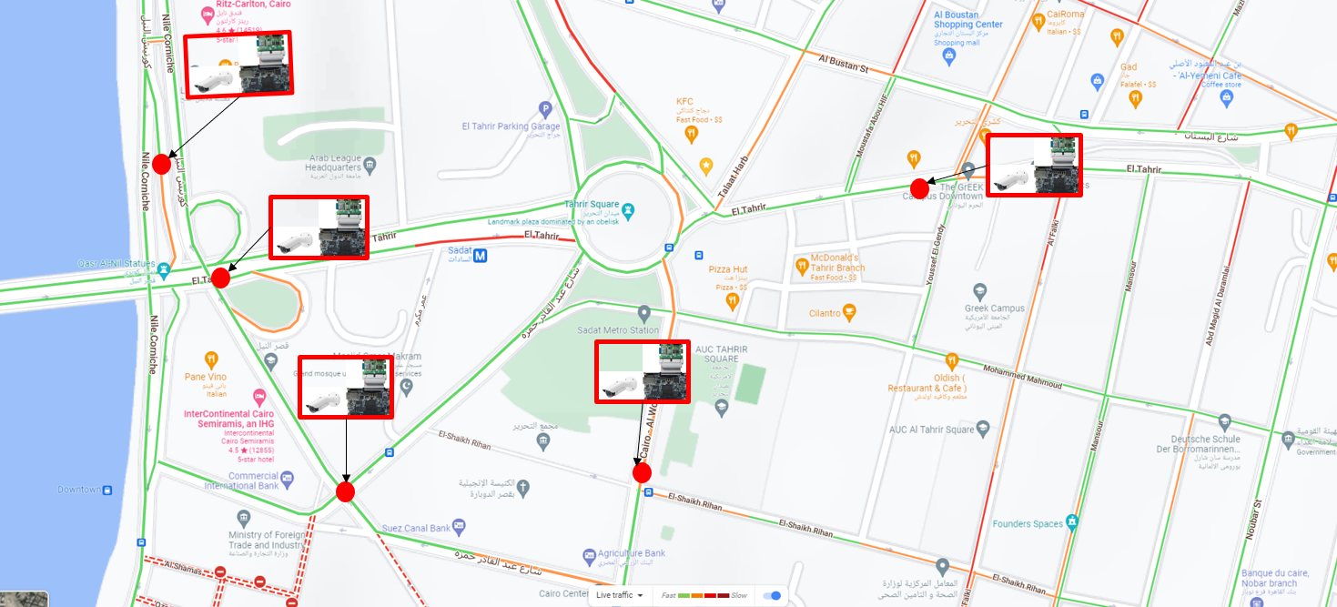
Fig 41 : Fitting system in Streets
Due to extreme costs associated with the current state of the art computer vision based networked monitoring systems, innovative computer vision system Implemented On De10 nano has be developed which are standalone and efficient in analyzing the traffic flow and tracking vehicles for speed detection. In this article, a traffic monitoring system is suggested that counts vehicles and tracks their speeds in realtime for multi-track freeways .
The big binefit of traffic flow analysis which is done in traffic management center , The ability of creating a traffic flow map may be like google maps BUT NOT USER DEPENDANT.
And is capable of tracking the vehicle trajectory and extracts the useful traffic information for vehicle counting. This stationary surveillance system uses a fixed position overhead camera to monitor traffic and RFID Readers to record cars ID.
8. Conclusion
The main aim of the project is to design and implement a smart traffic Monitoring system using Terasic DE10-Nano connectivity KIT with Intel SoC (FPGA Cyclone V + ARM A9),Analog Devices Evaluation Kit which enable to interface with analog and digital systems (DC 2581 ADC, DC2025 DAC , EVAL ADM3055 e-ARDZ ) and we succeed.
Also we have realized some features
Real-time car Monitoring Detection ,Counting , Tracking and Classifications
Real time Car speed Measurement implemented in FPGA LOGIC to achieve high speed.
Utilized a soft core NIOS II processor to do a lot of work with easy programming using c .
Our system can be upgraded to get a higher accuracy in speed measurement using phased array ultrasonic , a number plate detection and reading using OCR (Object Character Recognition ) can be implemented .
9. References
Imou, K., M. Ishida, T. Okamoto, Y. Kaizu, A. Sawamura, and N. Sumida. “ Ultrasonic Doppler Sensor
for Measuring Vehicle Speed in Forward and Reverse Motions Including Low Speed Motions ”.
Agricultural Engineering International: the CIGR Journal of Scientific Research and Development.
Manuscript PM 01 007. Vol. III
https://www.google.com/maps/@31.2060336,29.926094,18z/data=!5m2!1e4!1e1
https://techvidvan.com/tutorials/opencv-vehicle-detection-classification-counting/
https://pythonexamples.org/python-opencv-imshow/
https://forum.digikey.com/c/eewiki/logic/68
https://pyimagesearch.com/2018/09/26/install-opencv-4-on-your-raspberry-pi/
https://singleboardbytes.com/647/install-opencv-raspberry-pi-4.htm
https://docs.opencv.org/3.4/index.html
https://pyimagesearch.com/2018/11/12/yolo-object-detection-with-opencv/
10. Source Code
Source Codes FOR EM009 Project IN GIT HUB LINK :
https://github.com/eslamfayad/SMART_TRAFFIC_MONITORING_SYSTEM/
1 Comments
Please login to post a comment.
Eslam Fayad
Project source code
https://github.com/eslamfayad/SMART_TRAFFIC_MONITORING_SYSTEM