
EM039 » A smart management system to optimize renewable energy distribution
Renewable energy is unstable and unpredictable. A little bit more predictable are human needs of electrical energy. Small communities sometimes have private wind/solar plants and fast varying energy requirements that could be fed (so avoiding to get, and pay, energy from the local distributor) if only a precise and fast management system would be available.
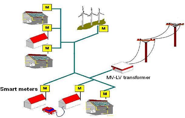
Our idea starts by considering a small community, up to 100-200 houses, where each one may have (or not) a private small solar/wind plant with or without local energy storage. A small public renewable plant may also be available.
Houses will share a power distribution network and will be connected to each other via a PLC (Power Line Communication) protocol. A power meter connected to a local management system (i.e. a DE10-nano board) will equip each house. A local sensor will measure instant power consumption (and production if applicable), calculate and update local power needs trends and manage a fast switching system in order to decide the best quantity of produced energy to store/use locally and to pump into the network. The same system will ask others the exact quantity of energy required locally and, if possible, acknowledge all requests received.
There will not be a central management system, all procedures will be shared by local controllers, by communicating to each other instant power surplus/requirements in order to minimize the total amount of energy got from local distributor.
Data collected about net energy amount flowed in/out every house will be used to build a periodical balance so each producer/consumer will pay for the surplus energy got only.
Power requirements/production can vary in less than one second, so each local controller should be able to activate its switch as fast as the overall situation will require. A fast data communication and processing is then required.
Purpose:
An improved environmental sensibility and renewable energy systems are permitting greater penetration of highly variable renewable energy sources such as solar power and wind power, with or without the addition of energy storage.
Current network infrastructure is not built to allow many distributed feed-in points, and typically even if some feed-in is allowed at the local (distribution) level, the transmission-level infrastructure cannot take care of many individual producers expectations.
Small communities of producers/consumers expect to exchange/store energy among their members in order to minimize the overall amount of energy bought from local distributor.
To do that, a smart grid management system able to follow rapid fluctuations in distributed generation and power requirements is required.
Applications:
Small communities, with a mix of producers/consumers, with or without energy storage systems, already fed by the same power network, can share their energy surplus/requirements by minimizing the overall feed-in/withdrawal from/to local distributor. The improved flexibility of the smart grid would contribute to ensure stable power levels on the main network, so permitting greater penetration of highly variable renewable energy sources such as solar and wind power.
Single producers can also minimize accesses to local distributor network with significant savings.
Target User:
Small communities, up to 200 houses, at least 20-30% of them with a renewable energy plant installed, with or without storage, fed by the same distributor

FeaturesA DE10-nano board equips each end point (house), where at least one “smart meter” measure instant power required/produced by the user and local storage availability. These info are processed on the board and, using also historical consumption data with predictive models, an instant power request/offer message is transmitted to neighborhood end points.
In a few tens of milliseconds each end point will be able to decide how much power deliver to one or more neighborhoods (to be used and/or stored), store locally, receive from neighborhoods or get/put from/to distributor.
Condition that can vary multiple times in a few seconds, due to the extreme volatility of power produced and requested.
In addition the smart grid allows for systematic communication between appliances and local controller, so permitting consumers (according to their willingness-to-pay) to be more flexible and sophisticated in their operational strategies.
Installing additional smart meters to high power consuming appliances and connecting them to local controller (DE10-nano board) can allow consumers to implement more strategic behaviors when they use energy.
They can configure their controller to activate non-critical loads when renewable energy is available, to enable access to distributor when crucial appliance must run only, and so on.
IoT technologies will be emphasized in order to do that and, to connect several local power sensors to local controller, some commercial/custom wireless/wired protocols will be implemented, in accordance with specific appliances communication capabilities.
IoT could also allows some appliances to be automatically "tuned" according to the overall results required, instead of simply be turned on/off. At the same time a global monitoring of AC network could be performed, with some nodes acting as Power Factor Analyzers/Correctors, Noise Measure/Limiters and/or Instability Detectors/Recorders. So doing, the energy sharing process can also be done on a quality basis.
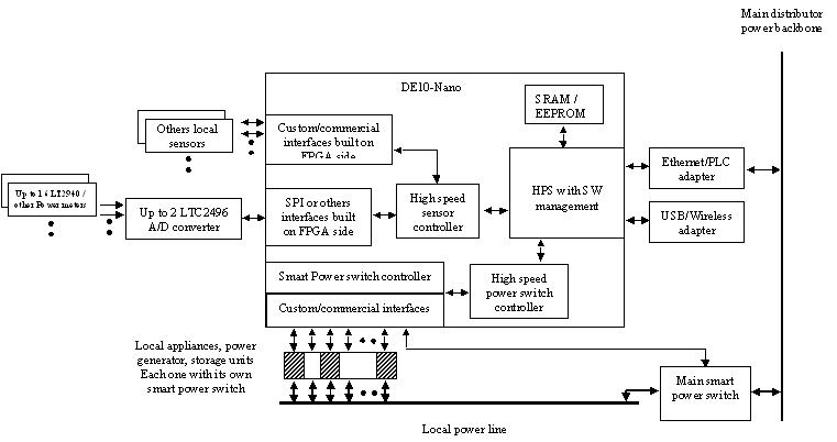
First picture shows local controller architecture block diagram. Power sensor interfaces will be designed on the FPGA side according to single unit requirements. Up to two 8 channels A/D converters can easily manage data from analog power meters. Other power meters (i.e. with digital output) can be connected directly through dedicated interfaces, built on FPGA side too.
A Smart Power Switch will equip each sensible appliance/power generator/storage unit, in order to perform a smooth, but prompt shaping of electric power used, stored or delivered to other sites.
Two custom controllers will be designed on the FPGA side to manage sensors and smart switches.
HPS will implement the best management policy in order to minimize external power requirements. It is connected to other sites by a LAN via a Power Line Adapter, so it can send/receive power requests/availability through electrical backbone.
An additional wireless adapter will allow remote management capability
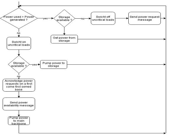
 The following diagram drafts a simple power management policy (under study at present) implemented in each HPS core.
The HPS core will host also a data warehouse built by historical data in order to better manage power need expectations. A remote monitoring system will also be implemented.
Other controllers and interfaces will run autonomously and concurrently, being implemented on the FPGA side.
Due to challenging problems involving high power AC line management, a DC demo project will be implemented, involving only low power components. Anyway overall goals and results will not be affected.
Due also to the availability of one DE10-Nano board only, a single end point system will be emulated. The controller will then be able to act according to local power measurements only, but commands to enable/disable its functions will be made available in order to easily upgrade the system to a multi end point scenario.
To cover most of possible scenarios, the end point demo system will have both a power, randomly variable, generator and an energy storage system. A bidirectional energy pump will also be implemented, in order to transfer electric power from storage to main line or vice-versa, according to needs and production.
A couple of local connection links will be implemented, to show IOT potential capabilities. Thanks to them, up to 16 local critical loads could be forced on/off by user (regardless of where he is) and/or by the controller itself.
Every communication link will be implemented on the FPGA side, by coding dedicated UARTs, leaving the HPS UART free for future multi end point connections and to perform balance/monitoring functions.
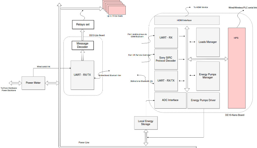
Close to the local site boundary we imagine to install an LTC 2947 Power Meter by Analog Devices, with a modified FW in order to send periodically the overall power flowing in both directions, from/to Distributor main backbone.
These infos are collected by a DE10Lite board via a wired serial link and sent through a Bluetooth link to the main controller (DE10-NANO) located somewhere in the house.
On the main controller side, a dedicated UART will receive these infos and make them available to local modules.
Power measure will then be used to decide how many local uncritical loads should be turned off, how much power should be pumped from battery to main line or vice-versa and, in a future upgrade, how much power could be made available (or should be requested) outside the local site.
According to the above decisions, one of the two energy pump drivers will generate a PWM signal with the right duty cycle in order to transfer the correct amount of power.
At the same time the Loads Manager module, according also to a local database populated with local loads priority/consumption infos, will decide which one should be turned on/off. This decision will generate a message that, through the same UART/Bluetooth link, will get to the DE10Lite, where it will be received, decoded and will produce the requested action by turning on/off a relay switch.
Concurrently the ADC controller will read the battery status; this value will be used by Pump Manager to stop/start charging/discharging the battery in order to avoid over/under charge dangerous conditions. The same info could be used in a future upgrade to offer/request outside a local/remote storage availability.
All this operations occur concurrently and according to fast varying conditions.
Anytime local users (or local appliances in a IOT scenario) will be able to force/unforce on some critical loads, in order to preserve/allow them from being turned off automatically.
We have provided a couple of way to do that, but potentials are obviously unlimited.
We coded a second UART, connecting it to another Bluetooth module, and a Sony SIRC decoder, with a cheap IR receiver connected to it.
Thanks to the above modules local users can send force/unforce commands to the system by using a simple IR remote controller (in the demo a Sony one) or a mobile phone/tablet equipped with a Bluetooth/Serial application.
By connecting to the UART a GSM/GPRS or a WI-FI module, users should be able to send commands from anywhere.
At the same time, users can receive info on the system status through the same link (feature not available in the demo, but easy to implement if required).
Basic FSMs operations are described in the first flow diagram
Taking advantage of hardware parallelism, FPGAs exceed the computing power of traditional processors by breaking the paradigm of sequential execution and accomplishing more per clock cycle.
In this project every appliance/generator/storage device can be analyzed and managed by its own custom processor, thus allowing a double advantage. First of all, every peripheral is served without any latency, so to improve the overall functionality. On the other side the processor is free to perform high level management tasks.
The several (sometimes custom) interfaces requested by sensors could not be implemented by a single processor, in addition changes over the time might required severe software upgrades.
Being reconfigurable, FPGA chips can keep up with future modifications that might be necessary. As a product or system matures/change/is added, functional enhancements can be set without wasting time redesigning hardware, modifying the board layout or the overall software architecture.
The system can easily scale to a bigger size simply adding the interfaces/peripherals needed. Thus without any change neither in the overall architecture nor in the core speed, because most of processing requirements are managed by FPGA.
Changing sensor/switch interface/protocol is also straightforward, any custom data flow management can be easily implemented on a FPGA. So designers can take advantage of an unlimited freedom, allowing them to choose the most suitable device for every need.
Low cost FPGAs let designers to easily afford complex designs of uncertainly outcome too, then allowing a straightforward growth.
The use of an Altera-Intel FPGA-SoC will grant also the following goals.
First of all, a SoC FPGAs offer the advantage that a custom ARM microprocessor derivative can be created instantly, right on the desktop, by adding the needed peripherals.
I.e. in this project every single controller must be equipped by several UART (that must run simultaneously) in order to communicate with all meters and all IOT appliances available in one house and with the ones outside.
Each controller can be different, in order to communicate with a different number kind of receiver and should be easily updated as soon as working conditions will change (i.e. new appliances).
System design does not have to accept compromises due to the lack of off-the-shelf processor derivatives, and every issue can be differentiated both in hardware and software.
The FPGA flexibility, first of all, allows designer to faithfully adapt every site controller to local requirements and last, but not least, to make it more difficult for competitors to copy or emulate.
Purpose:
An improved environmental sensibility and renewable energy systems are permitting greater penetration of highly variable renewable energy sources such as solar power and wind power, with or without the addition of energy storage.
Current network infrastructure is not built to allow many distributed feed-in points, and typically even if some feed-in is allowed at the local (distribution) level, the transmission-level infrastructure cannot take care of many individual producers expectations.
Small communities of producers/consumers expect to exchange/store energy among their members in order to minimize the overall amount of energy bought from local distributor.
To do that, a smart grid management system able to follow rapid fluctuations in distributed generation and power requirements is required.
Applications:
Small communities, with a mix of producers/consumers, with or without energy storage systems, already fed by the same power network, can share their energy surplus/requirements by minimizing the overall feed-in/withdrawal from/to local distributor. The improved flexibility of the smart grid would contribute to ensure stable power levels on the main network, so permitting greater penetration of highly variable renewable energy sources such as solar and wind power.
Single producers can also minimize accesses to local distributor network with significant savings.
Target User:
Small communities, up to 200 houses, at least 20-30% of them with a renewable energy plant installed, with or without storage, fed by the same distributor
FeaturesA DE10-nano board equips each end point (house), where at least one “smart meter” measure instant power required/produced by the user and local storage availability. These info are processed on the board and, using also historical consumption data with predictive models, an instant power request/offer message is transmitted to neighborhood end points.
In a few tens of milliseconds each end point will be able to decide how much power deliver to one or more neighborhoods (to be used and/or stored), store locally, receive from neighborhoods or get/put from/to distributor.
Condition that can vary multiple times in a few seconds, due to the extreme volatility of power produced and requested.
In addition the smart grid allows for systematic communication between appliances and local controller, so permitting consumers (according to their willingness-to-pay) to be more flexible and sophisticated in their operational strategies.
Installing additional smart meters to high power consuming appliances and connecting them to local controller (DE10-nano board) can allow consumers to implement more strategic behaviors when they use energy.
They can configure their controller to activate non-critical loads when renewable energy is available, to enable access to distributor when crucial appliance must run only, and so on.
IoT technologies will be emphasized in order to do that and, to connect several local power sensors to local controller, some commercial/custom wireless/wired protocols will be implemented, in accordance with specific appliances communication capabilities
-------------------------------------------------------------------------------------------------------------------------
According to our first idea, we designed a small model of a smart meter that would equip each site of a small community.
To reduce technical problems not directly connected to our main goals, we have assumed the following hypothesis:
1) Main power backbone will be sourced by a DC power supply at low voltage (12V), although some AC metering functionalities will be investigated and implemented (see Regional Final upgrade section).
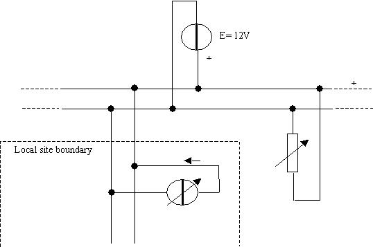
2) A local, grid connected to main backbone, renewable (solar/wind/etc) plant, will be emulated. A second DC power supply, configured as variable current source and directly connected to main backbone, will be placed for that purpose.
3) There will be also a local energy storage system, able to pump energy into or to be charged by the main power backbone.
4) In addition, there will be emulated up to 16 different electric loads (local appliances or so on), each one with its own power requirements/priority, manually and/or automatically on/off switchable according to the user's willingness to save conventional energy.
5) Site to site talking/messaging capabilities as well as local data warehousing will be implemented as a basic structure only due to just one DE10Nano board availability. In order to allow future developments, commands for the local HPS to control overall procedures will be anyway implemented and made available.
The use of Intel FPGA will allow us to implement commercial and custom protocols in order to better communicate with appliances and between sites. Some examples of that will be provided. FPGA flexibility will give us also the capability to adapt smart meters to each site, by varying connections modalities.
A reduced block diagram of the smart meter first presented will be realized, with the aim to demonstrate overall potential capabilities in a small model.
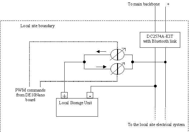
A DC power supply, at fixed voltage (12V) and with enough power capability, will be used to emulate the main distributor backbone. Some manually variable loads will also be connected to the above power line. This scenario should emulate a real condition where multiple users are connected to the same distributor line. Each one can randomly get energy from it but, at the same time, the main backbone will be able to supply more energy if requested by each user, keeping also the power line voltage at the nominal level.
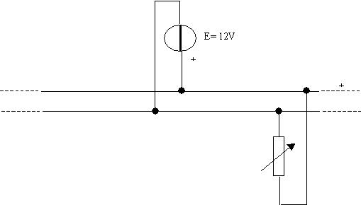
On the local site a DC current supply will be provided, as renewable grid connected plant emulation. This generator will be able to pump a manually variable current into the main backbone, but from the local site side.
On the local site main switch cabinet, a power meter based on Linear DC2574-KIT will be installed. This device will measure the overall net power flowing from the main distributor backbone to the site and viceversa. A slightly changed functionality of the above KIT will be implemented as follows. The original firmware will be updated by adding a serial transmitting function in order to send, every second, the overall power measured, packed into a 32 bit frame (one byte for synchronizing requirements followed by a two complement, 24 bits power measure).
The LINDUINO ONE® Uart will send packets to DE10Nano board through an upstream Bluetooth connection, realized by an HC-05 daughter card, to be easily found everywhere for a couple of bucks.
A AC metering function will also be developed in order to test commercial products/protocols (see Regional Final upgrade section)
Inside the same main switch cabinet, a Bluetooth remote controlled relays set will also be installed. This device, using the downstream side of the same Bluetooth link, will receive commands from DE10Nano board in order to switch on/off dynamically local loads accessible by main switch cabinet.
Taking advantage of Intel FPGA flexibility, a second/third/nth similar device could be easily planned in different places, by simply adding more UARTs to the DE10Nano FPGA side.
A DE10-Lite Board will manage commands receiving/decoding functionalities inside the main switch cabinet and will drive the relays set. The DE10-Lite will host a UART RX functionality, followed by a message decoder in order to drive the relays set.
The above functionalities can be easily implemented in any low cost CPLD/MCU Arduino-like.
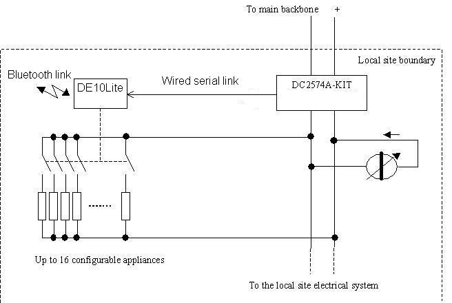
To allow the model to be as more general as possible, an energy storage system will be added. This will be achieved by a Pb battery connected, through a bidirectional power interface, to the power line.
The above interface will make possible to pump energy (with dinamically configurable values, time shapings and limits) from the battery to the main power line or viceversa, according to commands received by the DE10Nano board.
This interface will be built by using two current controlled power driver with isolated outputs, usually used as LED driver, widely and easily available. These drivers can be controlled by I2C/PWM signals and are capable to adapt their outputs to a wide voltage range, without affecting the current programmed value. Thanks to their usual high conversion frequency, they are also able to follow fast dimming commands. This kind of devices are the most similar to grid connected AC inverters, as well as easy to be controlled by external PWM signals.
As first choice, we planned to use Linear DC2424A-KIT, thanks to its double output interface. After a first datasheet analysis we moved to others devices (MEANWELL LDD-L), able to guarantee isolation between outputs and a higher operation voltage. We will use two devices, one to pump power from storage to the power line and one for the opposite direction.
The storage status will be monitored by DE10Nano ADC. To do so, an ADC channel will be configured as differential to avoid grounding problems. This channel will be connected to the battery, through a voltage divider (useful to simulate battery charged/discharged status). According to battery status, the controller will stop/start charging/discharging processes (with the capability to dinamically shape power profile) and will be able to acknowledge/decline/send power requests from/to other sites.
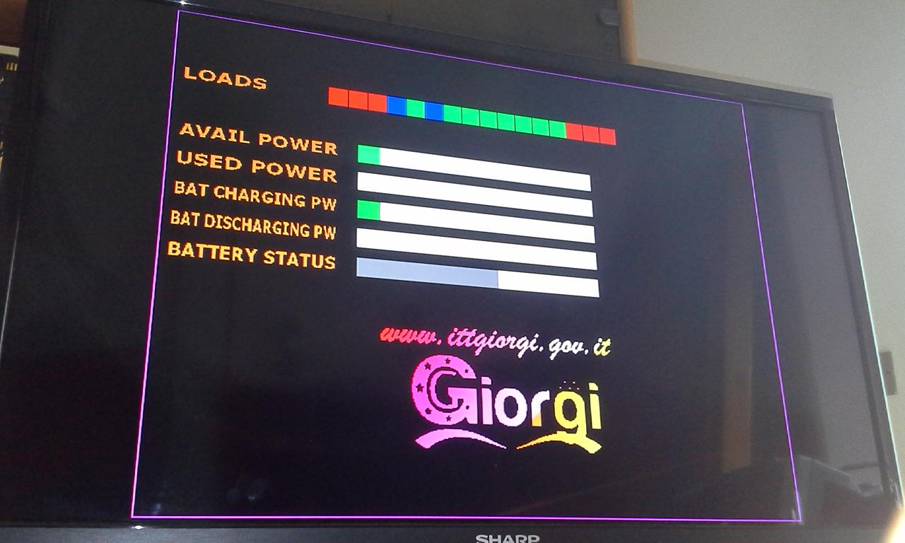
Start/stop/shape functions will easily be performed by two 256 step PWM signals generated by DE10Nano board, battery status will be shown on a TV monitor via HDMI interface by a bar graph..
On the same monitor four more bars graph will be shown, two to indicate the amount of power available or requested (locally) and the other two to show the instant power pumped from/to local battery.
The system will show also the loads status as a 16 blocks bar. Each block will change colour according to the related load's status: Green if active, Red if turned off, Blue if forced on, as follows:
In this model the same amout of power available/requested will be pumped to/from local storage at any time, due to a single site scenario. In real conditions local available and battery charging powers could be different from each other (as well as used and battery discharging ones) due to a site to site power exchange.
As shown in the block diagram, the system designed can be divided into three sections, with in addition the DE10Lite as daughter board.
Two UARTs, one IR SIRC decoder, the ADC and the HDMI encoder belong to this section.
The first UART establishes a bidirectional serial link (through a pair of Bluetooth modules) between the DE10-NANO (master) and the DE10-LITE boards. The upstream flow (9600 bps at the present) concerns the power measure data that the LTC2947 sends every second. The downstream one (9600 bps too) carries the turn on/off commands directed to local critical loads.
As described in the following Regional Final upgrade section, when using a commercial AC power meter, a further bidirectional link will be needed. This link will be reserved to the MODBUS protocol between main controller and power meter.
The second UART is used as RX only (at the present) and is connected to a third Bluetooth module. It is useful to receive force on/off commands from local/remote users through mobile phone, tablet and so on. An easy upgrade could be the use of a GSM or WI_FI module instead of the Bluetooth one, in order to allow greater distance communications. Another upgrade as much easy as the first one could be the addition of a TX link, so users could be kept informed about the system status, no matter where they are.
The SIRC decoder, connected to a IR receiver, like the TSOP1738 by Vishay Semiconductors, makes the system able to receive force on/off commands by a simple IR remote controller. The choise of SONY SIRC protocol is absolutely random, we could have chosen any protocol of the hundreds existing.We just highlighted how the FPGA potential can make everyday life easier. This goal can be achieved, for example, letting users free to use their usual devices, thanks to the ability of FPGA to implement any communication protocol.
We will use just one channel of the ADC available on the DE10 Nano. This channel, configured as differential, will be used to check the local storage charge level. Other channels could be used in a future upgrade to get analog info from other appliances, or to convert other power measures (i.e. the power generated by local renewable plant, etc). We will use an appropriately modified version of demo code (written in verilog and distributed inside the DE10Nano CD), together with a module (expressly written for this purpose in VHDL) in order to perform periodic measurements, to convert results to an 8bit range and then send them to other modules.
We will reuse the demo code of HDMI encoder, but we will add to it all needed parts in order to display all info requested, last but not least, our logo!
As result we image the DE10Nano board installed close to the home TV and connected to it via HDMI interface.The system will autonomously receive/send info from/to other sites via the HPS UART, will receive instant power info from the main switch cabinet via Bluetooth link, will send commands to turn on/off local appliances, pump energy from/to local storage, in order to minimize main distributor power withdrawal.
Any time, the local user, while looking at HDMI channel on its TV to check the overall situation, can use its usual TV/VCR IR remote controller (no matter which one) to force on the air conditioning system and/or the microwave oven when needed, then switch back to its TV program.
Independently of him, his wife, miles from there, can text a message via mobile phone, to force on the dishwasher and so on.
In this sections we will have two main modules, both of them able to work concurrently, autonomously or independently selectable by HPS: a loads manager and a power pump system.
According to instant power measure, this module will activate/deactivate local loads by sending messages to the relays set via a Bluetooth link. A local configuration table will be populated by loads specs (at present power requirements and priority). Users should obviously adapt the above table to their needs by using a smart video interface (at present not implemented), they can also assert/deassert anytime a "forced flag" in order to avoid some load being stopped by the Manager.
The load to be activated/deactivated will be chosen according to its priority and to requested power, with the goal to minimize the overall deactivation number and to keep on as many prioritary loads as possible.
Loads status (active/stopped/forced) will be shown on a TV monitor via HDMI interface. as well as instant power flows.
This system can be enabled/disabled by HPS according to power requests/offers coming from other sites. HPS can also add/subtract to/from power values measured by the local meter the instant power received/sent from/to other sites, in order to shape accordingly the Load/Pump managers behavior.
According to instant power measure and storage status, this module will activate one of two energy pumps, by generating a PWM signal with a duty cycle dinamically dependent of the above power value. An instant power surplus will generate a battery charging process, otherwise any power lack will be instantly covered by a storage discharging one.
These processes will involve an instant power value dinamically dependent of instant overall power available/requested. This power shaping will be achieved by a dinamically variable duty cycle signal.
There are two PWM drivers, each one for one power direction. They will be activated in turn by a controller that, after receiving the power measure and the battery status, will send to the right one the start command and the power value to be pumped.
These processes will be also shown on the TV monitor via HDMI interface
As usual, this system can be enabled/disabled/shaped by HPS according to power received/sent from/to other sites..
As told in the previous sections, we have decided to develop just a basic application on the HPS side due to following reasons.
First of all, not having a way to connect at the least two DE10Nano boards (because we received only one, but the project should involve many of them connected to each other), more sophisticated features would be, at the present, useless.
Our idea would be also to leave HPS managing statistical functions, balancing/accounting functionalities in order to divide overall costs between users, to forecast consumption behaviors and so on. All functions almost hard to simulate (and quite useless too) a single user scenario.
We anyway decided to reserve the HPS UART for inter-site communication, by connecting to it a PLC modem or some other transmission links.
Although we developed a HPS basic applicationonly, a future upgrade with more functionalities would be quite straightforward, because every module developed can be tuned/enabled by expressly designed and implementer flags.
Without any lack of generality, we will imagine up to 16 high consuming (and/or critical) loads (local appliances like air condictioner, irrigation system, dishwasher, etc) being powered by a central switch cabinet, where we can install a relays bank in order to activate/deactivate them according to the power management system commands.
A distributed power situation regarding other appliances could be easily managed by adding to each of them a cheap Bluetooth (or any other connection module) receiver/decoder.
We will decide to use a DE10-Lite board. Any other cheap MCU (like Arduino, etc) would be good for the needs.This board will be connected to main controller (DE10Nano) through a bidirectional Bluetooth link.
So we will code a UART and a message decoder in VHDL, then connect this board to a cheap relays set and to a Bluetooth module. A very simple protocol will make the system complete: one byte messages, each one formed by LSB nibble to address the specific load and one bit to active/deactive it. These messages will be sent from DE10Nano board via the downstream Bluetooth link.
The power measurements, performed by LTC2947 kit, will be sent periodically to the main controller (DE10Nano board), through the downstream side of the above Bluetooth link.
When the MODBUS AC meter will be used, aadditional half duplex link should be realized (see Regional Final Upgrade section).
Smart Meter performance analisys
First of all the system should be able to elaborate in real time all expected power fluctuations. In a 50/60 Hz distribution network a 100/200 ms cycle can be the fastest possible. We used the LTC2947 meter with a 1 second measurement cycle and we assume that value acceptable also for a real system, to avoid too frequently on/off messages due to transient conditions.
A MODBUS AC meter has been tested also (see Regional Final Upgrade section) with same measuring interval, although it could work faster.
One second also is an acceptable time for all boards in the inter-site network to exchange/elaborate messages to each other.
We used also a 9-bit precision for power measurement (256 step for positive and the same for negative values) assuming that a reasonable limit (LTC2947 allows up to 24 bit measurement like the AC meter tested).
So doing we can measure up to 3 KW at 12W step in both directions.In the model we downgraded respectively to a 13W and 50mW step. This values could be considered acceptable too.
Up to 16 local loads should be an acceptable limit too, although easy to be changed, it will suit majority of user needs.
Without any lack of generality, a couple of user connection ways have been implemented:
1) Bluetooth link via mobile phone;
2) IR link via traditional remote controller.
Each one has a dedicated RX module designed on the FPGA side. They can easily be expanded in order to allow many channels and more protocols, although they appear to be enough.
To control appliances a single 8-relays set has been provided. Using a DE10Lite board as UART/Message Decoder, another Bluetooth link connection with the main controller has been implemented.
At the same time, expanding the connection channels should allow a more distributed appliances control. Thanks to FPGA flexibility, it should be easy to implement more connection channels (Bluetooth, GSM, WI-FI, etc) to directly control appliances not accessible by main switch. IOT functionalities, often available on modern appliances, could be used to do so.
Local energy storage charging/discharging processes have been implemented with energy pumps controlled by PWM signals.
In a real system, these functionalities should be implemented by grid connected AC inverter, which power output stages are usually controlled by PWM feedback signals. At the same time the above kind of inverters are usually programmable via standard interfaces, like RS485, etc and commercial/proprietary protocols (i.e. MODBUS, both of them already implemented and tested).
No matter which interface/protocol will be available, thanks to FPGA flexibility it should be easy for any designer to substitude present encoder module with the one needed.
It should be also advisable to develop a modules library in order to suit the majority of commercial inverter/IOT interfaces.
In addition it should be also possible to implement more power meters on the same site. This would allow to have a more precise measurement process. To do so, many ADC channels, at present available, could be used, although it appears that installing many AC meters sharing a RS485 link, could be preferable.
A basic SW flow on the HPS side has been implemented, due to the single point scenario. Anyway HPS can easily modify the power values that FSMs will use to manage energy pumps and loads. It can control overall processes too, by enabling/disabling/shaping the above functions.
We decided also to let any local HPS responsible to manage the overall energy got from other sites, so it should be advisable to perform a periodic global accounting process (at present not implemented).
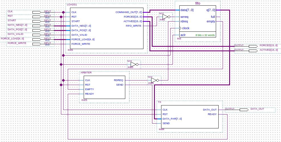
Following there is a live block diagram of the overall system structure
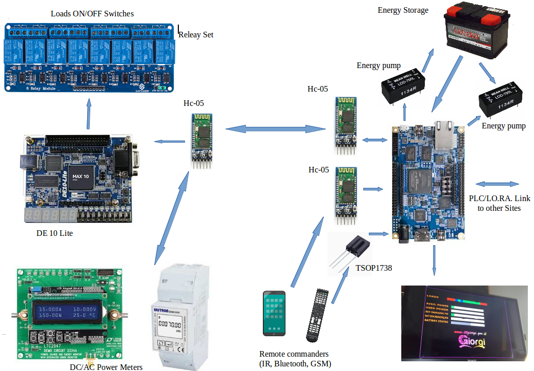
Where the DC power meter (LTC 2947-KIT) has been upgraded to a commercial available AC one (see Regional Final Upgrade below)
Let's go deeper into each part, starting from the DE10-Lite daughter board on the left.
This is the top schematic, as appears on Quartus .
On the left side there is the UART RX module, used to receive the turn on/off commands from the main controller. The data coming from the LTC2574-KIT power meter passes directly to he Bluetooth module, without any operation performed by this board.
On the right side there is the decoder module. As soon as one message is received, this module will decode it and will turn on/off the corrispondent relay. A visual message will be also provided, both by onboard leds and 7s displays.
As described above, this is a very simple block, easy to be implemented in any MCU Arduino-like or even less powerful.
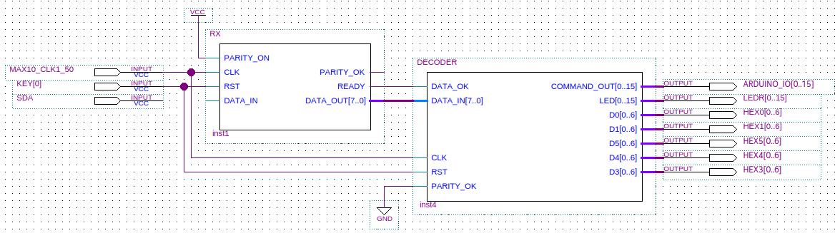
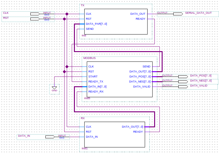
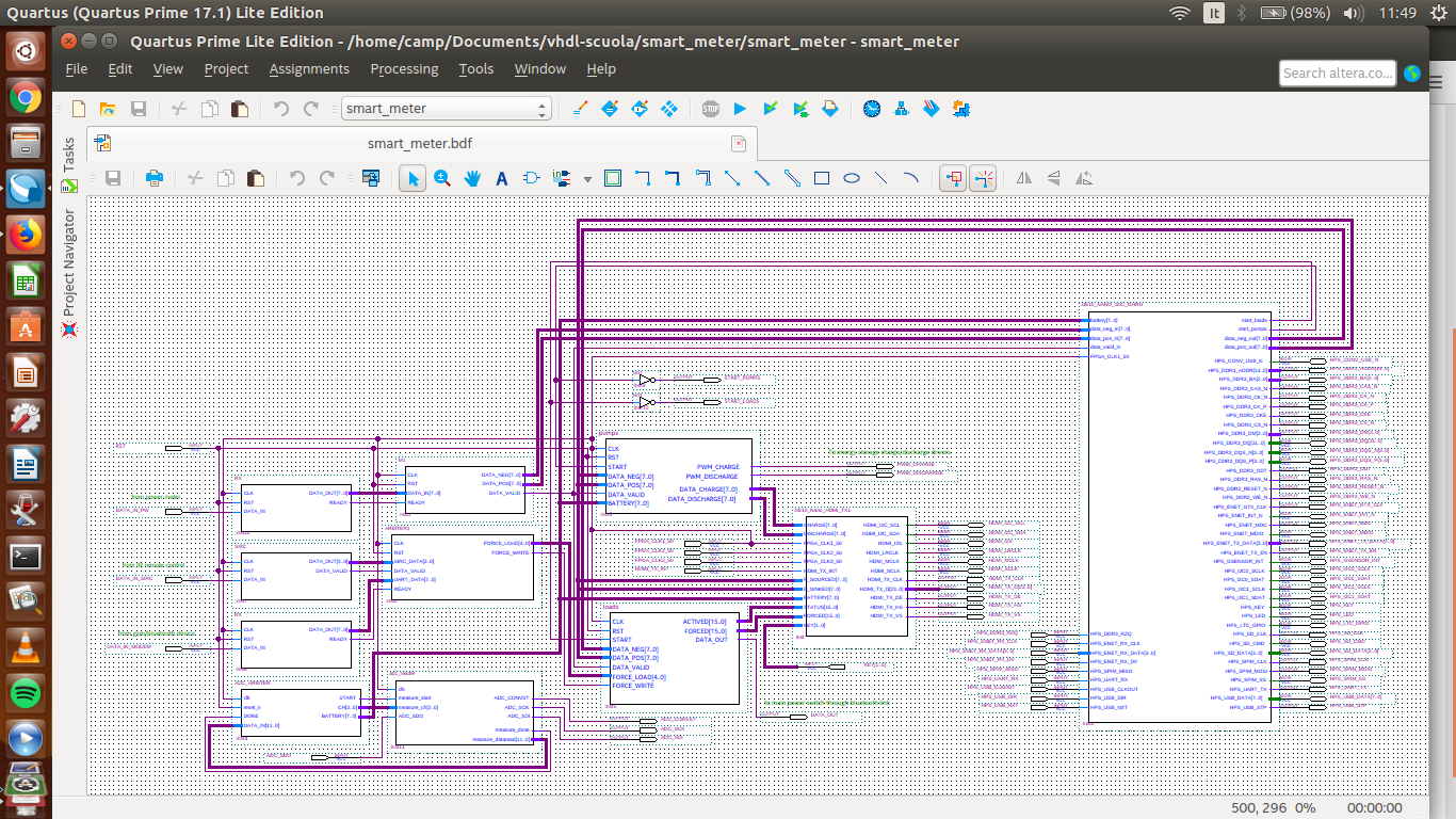
This is the FPGA side top schematic as appears on Quartus
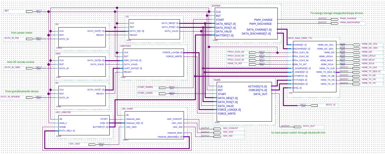
As described below in the Regional Final upgrade section, the HPS side has been added.
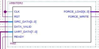
On the upper left side there are three communication modules, two RX-only UARTs and one IR SIRC receiver/decoder as shown in the following picture.
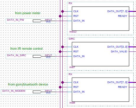
Their work is simple: waiting for incoming messages, then decoding them and putting the payload on the registered out port. There is no need of buffering due to the transmitters low speed.
We decided to use a very simple protocol, so there is no need of subsequend elaboration stages.
The data coming from Power Meter is in a 4 byte format: 55DDDDDDh, where the first byte is added for synchronization purposes only, the last three bytes are the measure. Every measurement requires then a 4 bytes transmission.
Force/Unforce loads messages have these patterns:
From IR controller: AAAA - the 4-bit address of load to be forced/unforced with an implicit toggling feature (every message will toggle the addressed force flag.
From gsm/bluetooth: FXXXAAAA - where F should be 1 to force on, 0 to unforce. AAAA is the load address, XXX are don't care bits.
The above modules have been coded in VHDL.
As described in the Regional Final Upgrade section below, the upper RX module would be used in a DC demo only, due to the development of a AC metering interface.
On the lower left side there are two modules, designed to get the battery charge status.
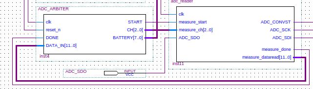
On the right there is the ADC interface module, taken by the DE10-Nano System CD and modified in order to use only one channel in differential mode.
The module on the left has been developed in VHDL to implement a FSM that starts the ADC measurement process periodically, then wait for its end and converts the results in a 8-bit range.
This module could easily be upgraded to perform multiple measurement processes, over other channels. In this way in a future release it could be possible to receive and process analog data from renewable generators and/or load sensors.
The battery level is then sent to HDMI interface and to HPS in order to perform all needed processing
Power measurement data, coming from Power Meter via Bluetooth link, are then processed by the following module, called M1
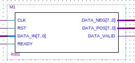
Its first purpose is to get synchronized with Power Meter bursts, so it waits for the sync byte (55h) and then collects the three following bytes. A watch dog feature will reset the main fsm in case of wrong formats received or missing bytes.
Data collected (24 bit in two's complement) are then processed in order to extract two unsigned 8-bit fields, one for positive and one for negative power values.
The processing window is easily selectable, in order to adjust the sensibility at the desired value. Due to low power levels used in the demo, we have decided to select the LSB 8-bit field. In this way the system sensibility will be 50mW (as provided by LTC2574-Kit).
This module, should be used too for a DC demo only, please see the Regional Final Upgrade below.
This module gets forcing messages coming both from IR controller and Bluetooth link, then it builds an internal command according to them. This 5-bit command carries the address of load to be forced/unforced and the MSB bit for the command itself, like the following pattern: FAAAA. As usual F = 1/0 to force on/to unforce.
All info processed by the above modules are then sent to the core units: Pumps and Loads Managers. Both of them are individually enabled/disabled/controlled by HPS. In the first demo the enable pins was driven by two external switches.
As described in the Regional Final Upgrade chapter below, the power info will be sent to HPS. It will then enable/disable both core managers and modify the overall power measurements according to values received from other sites
This module is responsible to generate the right PWM signals in order to pump energy from storage to the main power line or vice-versa. To do that it processes data coming from Power Meter and storage charging status coming from the local battery by ADC module.
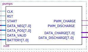
Let's go a little bit deeper into it
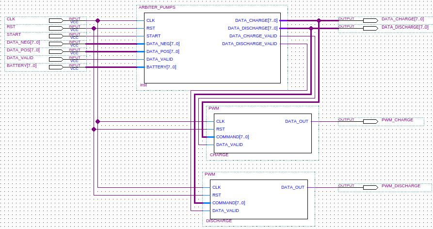
As it can be seen from the above picture, there are two identical PWM drivers on the bottom. They generate a 200 Hz PWM signal with duty cycle according to the 8-bit value (0 to 255) received. Both, signal frequency and step's number can be easily changed, if needed.
At the same time these modules can be easily replaced with another ones in order to match different power pumps interfaces and protocols (I2C, CANBUS, etc).
The top module processes instant power and battery status to decide how much power pump and to which direction. In the demo a default policy has been implemented as follows:
1) Power pumping values equal to power available/used ones in both directions
2) Stop pumping from battery if its charge level is under 30%
3) Stop pumping into battery if its charge level is over 90%
These parameters can obviously been changed, by users and/or by HPS.
The top module generates also all necessary data to drive the bars graph on the TV
The ARBITER_PUMPS module has an optional input port (at the present commented as said above), that could be used by HPS to manage the instant power value received/sent from/to other sites. This feature allows this module, by adding/subtracting the value received by HPS to/from local measured power, to shape the power pumped accordingly to intersite exchanges.
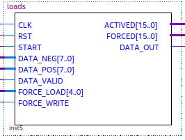
This module receives instant power data and forcing messages. It generates commands to be sent back to DE10-LITE board in order to switch on/off specific loads, according to a specific policy.
It generates also the loads status data to be displayed on the TV monitor.
Let's go a little bit deeper into it too
The core module has a loads table where the users can characterize them, by registering the power needed, the priority, and other similar infos. In the demo we will limit to the above two values.
Some FSMs are designed to perform the following actions continuously and concurrently.
1) As a force/unforce message is received the correspondent force flag will be set/cleared
2) As a negative power measure is received the least priority (and unforced) load status flag will be cleared
3) As a positive power measure is received the most priority (and unforced) load status flag will be set
4) As soon as a a status flag changes, a command will be generated and sent to a FIFO buffer. At the same time, loads status will generate signals toward the TV monitor interface in order to display the updates.
The two modules at the bottom center are respectively:
On the right a UART-TX used to send commands to DE10-LITE through the bidirectional Bluetooth link.
On the left a simple FIFO-reader machine, that waits for UART to end the command sending process and then reads the following command from the FIFO memory if available. It generates at the same time the needed start signal for the UART.
Like the previous module, the LOADS_MANAGER can be managed by HPS too. It can be enabled/disabled (in the demo by a external switch) and it has an optional input port (at the present commented), that could be used by HPS to manage the instant power value received/sent from/to other sites. This feature allows this module, by adding/subtracting the value received by HPS to/from local measured power, to turn on/off the local loads accordingly to the overall power available due to site-to-site exchanges
.
This module is used to show the overall system status (i.e. power measure, power pumps status, battery charge level and loads status) on a TV monitor.
It has been developed starting from a demo code available on the DE10Nano CD. We have rewritten a couple of source files, in order to display all information as above, and our logo on the bottom.
We plan to add some info related to power exchanges/overall balance as soon as a multi point scenario could be possible. It will be advisable also to allow users to manage local loads map through this video interface and/or by using available remote commander/mobile connections.
A simple SW flow has been designed in order to allow a basic multi point connection, as follows:
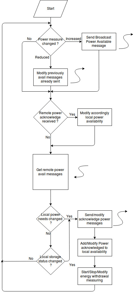
As it is shown, HPS will cycle endlessy and perform following functions:
1) Check local power balance and send a broadcast message with instant power availability (when applicable).
2) At the same time every remote HPS will get these messages and, according to their local power conditions, answer with a ack message if applicable. Every offer/ack message pair will report the power amount offered/acknowledged and a progressive number in order to avoid misunderstanding situations.
3) Following every ack message sent, the giving HPS should reduce accordingly its local power available (so letting the FPGA side system process the right value).
4) At the same time, the taking HPS would add the power being got to local availability and would start the energy exchange measurement for global balance purposes.
5) Every site could consider, as additional local user/producer, its local storage system in order to send or to be able to get, more energy to/from other sites. This option, considering the comparison between storage efficiency and energy cost, could be enabled or not, but is anyway possible.
As described in the Regional Final Upgrade section below, a very simple demo code has been written on HPS side, due to lack of other controllers connected.
According to our previous final summary, some of the most critical (from the industrial and commercial point ov view) points have been deeply investigated, in order to get our idea closer to a realistic implementation.
Our first prototype was using a Linear LTC2574-KIT DC power meter, but real applications will lead to AC power networks. So lots of commercial AC power meters have been studied, and we decided to add a VHDL module able to communicate with most of them via a widely available industrial protocol.
The power meter module we decided to use as example is a EASTRON SDM220 (http://www.eastrongroup.com/productsview/49.html) a single phase product with RS485 MODBUS RTU interface.
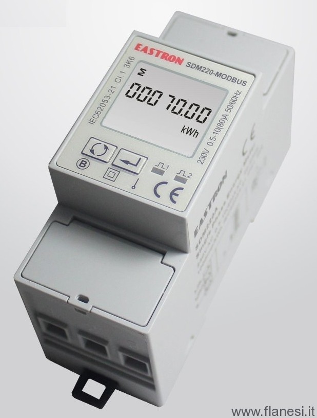
These kind of modules are widely used in renewable plants for metering and accounting functionalities. The MODBUS interface allows multiple module to be easily connected over a shared RS485 line in order to get multiple measure, not only from the main cabinet, but on single high consuming appliances.
This meter is ready to be installed on a din rail and can easily perform complex measurements (like power factor, reactive power, etc) in order to allow a reactive power management as talked above.
Similar three phase meters are widely available without any change in the communication protocol.
The MODBUS protocol, being essentially asynchronous, can be also easily encapsulated over a bluetooth link, allowing a fast connection procedure even if there are problems in setting up a wired network.
So, a MODBUS-UART interface has been developed, as shown in the figure. This module will substitute the RX UART + M1 module pair, and will be able to estabilish a half duplex link between the DE10NANO board and the power meter (no matter if via a wired or wireless interface).
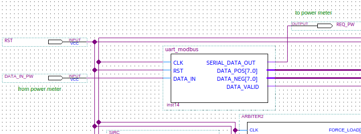 New Modbus-UART interface
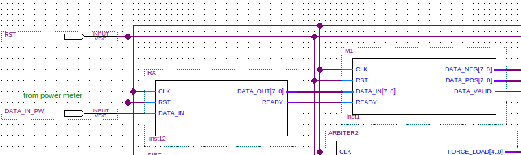 Previous UART interface
The MODBUS-UART interface will supply to the main controller the same info on active power available or used, so that all the other modules could work as before.
It has a bidirectional UART because the Modbus protocol require a half duplex connection. The module will produce a 8 byte request every second, then wait for an answer, decode it and produce two bytes as before, with the positive or negative instant power measure.
Let's go a little bit depeer into this interface:
At the bottom there is the UART receiver and at the top the UART Transmitter.
The central module is a sequencer that send every second the command to request the overall instant power and then wait for the meter answer.
According to the meter datasheet, it answers with a 9 byte message that embeds a IEEE 754 compliant floating point encoding of instant power measured.
The same module will then extract and convert this measure into the format previously planned, a 256 step value for both, positive and negative power.
All these functionalities have been developed in VHDL
The meter is then interfaced with the DE10Nano Board via a RS485/LVTTL converter, as shown in the following picture.
The first idea to evaluate some SEMTECH PLC/LoRa transceiver will be investigated according to technical documents availability. In the meantime we are studying another solution, also based on a PLC communication, but using commercial products already available. We are talking about Powerline Adapters, widely available by TP-LINK, NETGEAR and so on, like this one.
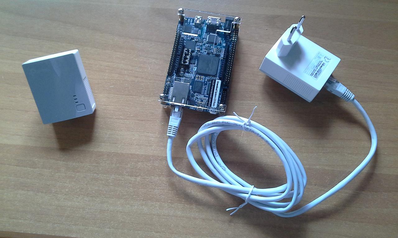
This kind of products are able to estabilish a gigabit ethernet network over power line, reaching up to 300 mt and up to 64 nodes at a very low cost and without any specific HW/FW interface to be developed (see as example the TP-LINK AV600 Specifications - https://www.tp-link.com/us/products/details/cat-5509_TL-PA4010-KIT.html#specifications).
Our first idea is to test a small network (up to 10 nodes) in order to find out the effective maximun distance covered, communication speed and latency time. Then develop a multi-hop application on the DE10Nano HPS side, where each node should be able to broadcast (via its Gigabit Ethernet over PLC interface) its subnet in order to offer its power surplus.
In case of no answer received, the site donating will text directly the nearest site of the neighborhood subnet, with a following local broadcast and so on.
By this way a nice side effect will be achieved, i.e. the priority for accepting nodes will be based on distance from the donating one. The closest is the accepting node, the highest will be its priority. This will lead to less waste of energy due to ditribution losses.
At the present a simple application based on libcurl library (https://curl.haxx.se/libcurl/) is under study, in order to make HPS able to communicate via Gigabit Ethernet over a PLC network created by the Powerline Adapter shown above.
According to our plan, a basic connection between HPS and FPGA has been developed in order to exchange instant power infos and commands to state machines.
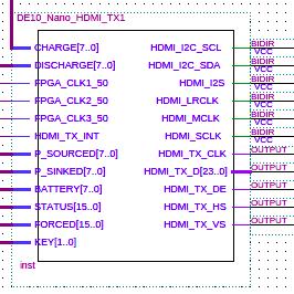
Following is a schematic diagram of the overall system
It is obviously possible to have the other version modified with the AC meter described above, where the UART-RX+M1 modules have been substituted by the MODBUS-UART one.
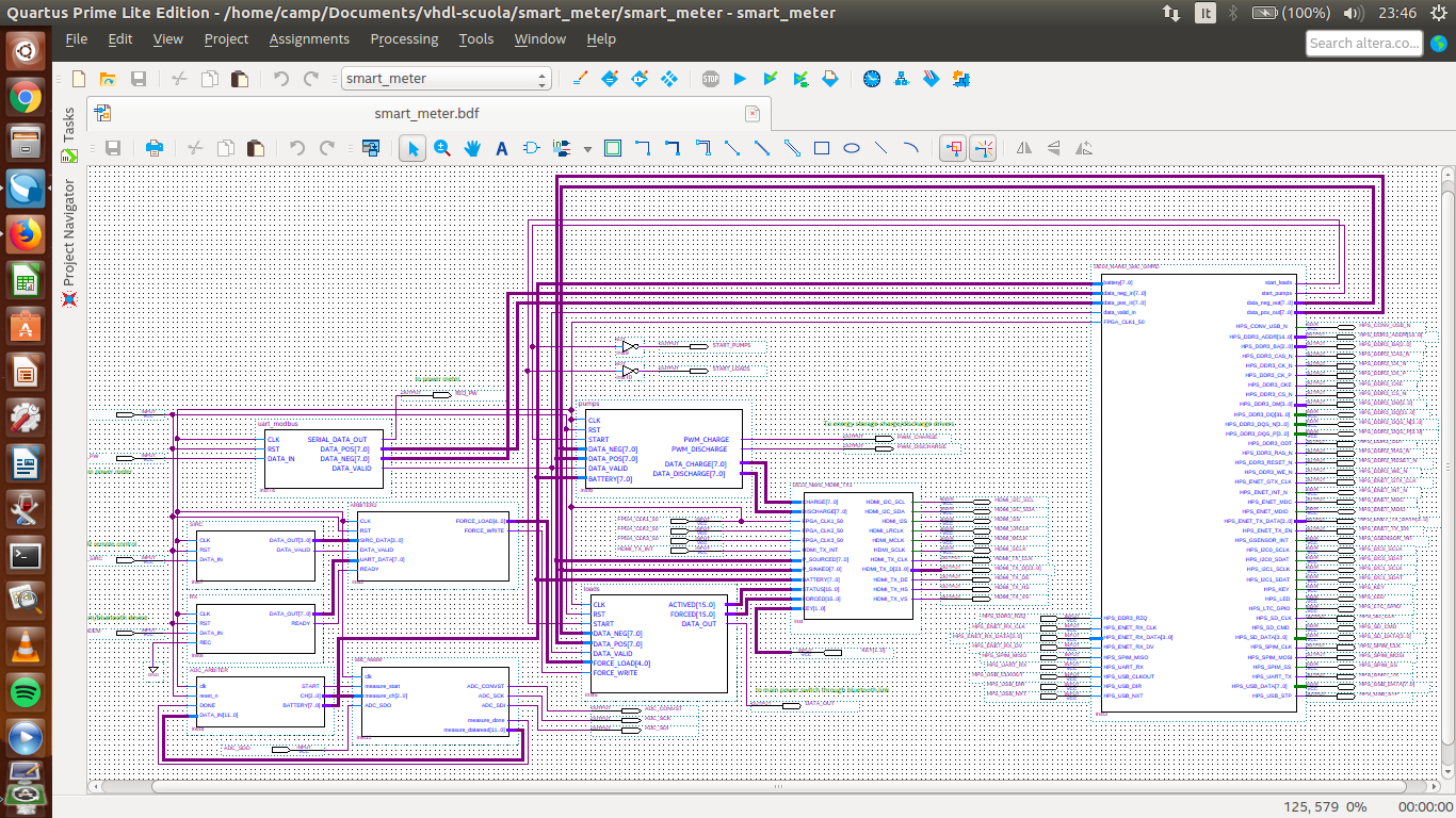
It's easy to recognize the HPS connected to previous system through a dedicated interface to be discussed further.
The overall system so upgrated, presents the following compilation report
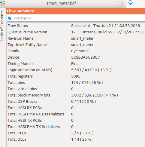
Going a little bit deeper into the project let's give a look at the SoC system as appear on Qsys
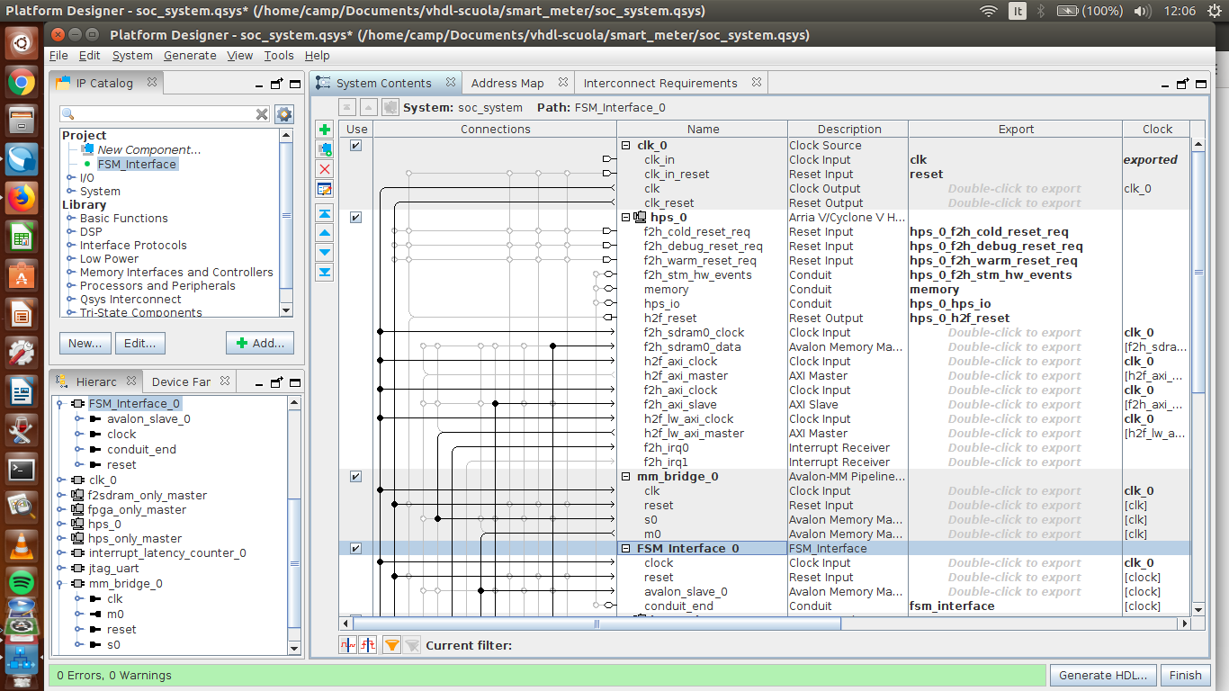
At the bottom there is the custom IP developed in order to interface HPS with the FPGA side, it has been called "FSM_INTERFACE" and talks with HPS via Avalon MM bridge.
This custom interface, written in VHDL, allows HPS to read the instant power (used and available) and the storage level. HPS can also write to some FPGA registers the amount of power donated/received to/from other sites and turn on/off the LOADS and PUMPS manager (previously controlled by local switches in the demo).
This interface is also able to perform some basic processing on these values. I.e. it adds/subtracts received/donated power to/from local measure in order to get the other modules aware about the total power available/requested, and other things like that.
Following is the I/O details of this interface.
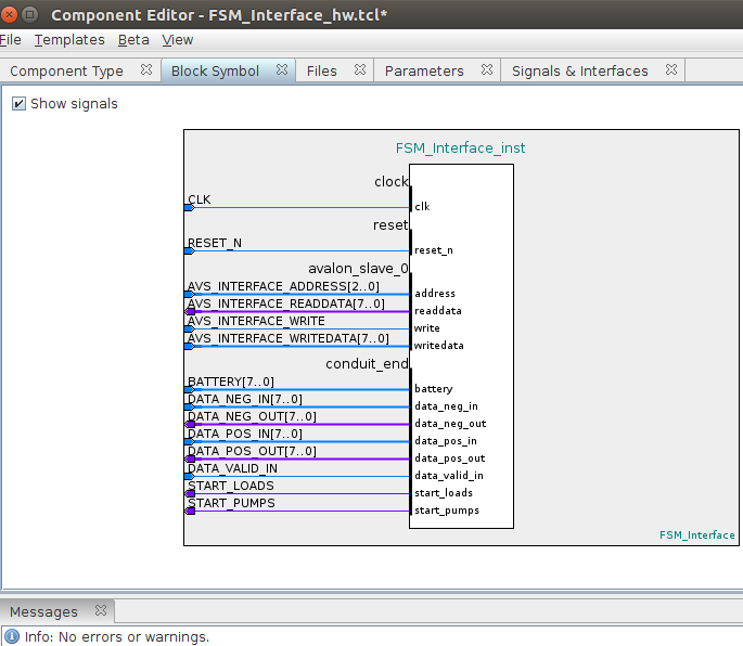
The basic code written for this interface allows HPS to increase/reduce power availability due to energy receiving/donating from/to other sites, to modify accordingly local storage charging/discharging processes and to control the on/off status of the PUMPS and LOADS modules.
These two last flags are also shown by a couple of leds.
Due to lack of a secont DE board, a simple C program has been written on HPS to test the overall system, as shown in the final part of the demo video.
This program writes on the FPGA registers power values at random intervals, simulating other nodes in a donation/receiving status.
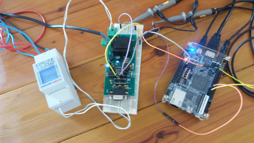
Following there is a picture of the Regional Final upgrade test bench, as described in the last section of the demo video:
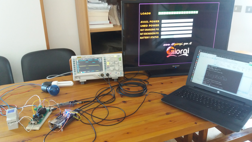
On the bottom left side there is the Modbus meter, connected to AC power distribution backbone, a couple of AC lights simulate variable loads. The dual channel scope shows in real time the MODBUS protocol handshake between the DE10 Nano Board and the power meter via the RS485/LVTTL interface. The Nano request at the bottom, the Meter answer, delayed by some tens of ms, on the top channel. The Nano board displays, as usual on the TV screen via HDMI interface, all collected and processed infos.
On the laptop, connected to the UART-to-USB Nano port, a terminal window gives access to the board linux kernel in order to launch the HPS application, previously copied on the micro-sd card.
As shown on the demo video, the system works like the previous release and, when the HPS application starts, it simulates random power donated or transferred from/to other sites at random intervals.
The system then acts accordingly, turning on/off loads, charging/discharging the energy storage, and so on.
https://github.com/scampeggio/Smart-meter---Innovate-FPGA-Contest-EMEA-2018.git
As first step of this project we can summarize overall results achieved and discuss them in order to plan further studies.
The basic structure of local site FPGA-HPS controller has been developed and tested. It can be considered as a good start point for the final product thanks to following features:
More testing over an real AC power network should be planned, although the measurement side has been enaugh investigated during Regional Final phase (see dedicated chapter)
Lot of tests should be performed in order to select (or design) the right charge controller (for a good storage system) and how to interface commercially available products, if possible.
We think that design a "flexible upgrade kit" could be the main goal. This kit should allow every local user with a renewable plant installed, to easily upgrade its AC inverter (with or without energy storage), in order to make it able to talk with the controller.
A deep study on power electronics and metering should be required also, in order to select the best way to pump AC energy to/from a power network with a controlled noise level and to best manage reactive energy.
A nice side effect of this system could be the possibility to implement a shared power factor correction functionality. Modern AC inverter can easily pump energy into the network with a desidered power factor (usually close to 1). So every site (local AC inverter) could be programmed to correct the overall power factor in order to reduce total community costs paid to main distributor. This scenario could lead to a situation where some sites will pump energy into the network in order to dinamically compensate the reactive energy produced by the others.
Some FPGA modules able to tune the AC inverter in order to pump energy with the right power factor should be studied
Our first idea was to use PLC modems connected to HPS side of each controller. We found some commercial product that could match the main objective to get a reasonable speed, in order to let the system updated in less than one second (see the Regional Final upgrade section).
The product already found (and under study) could be paired with some others like the SEMTECH transceiver EV8000/8600 (https://www.semtech.com/uploads/documents/ev8600.pdf).
The 8600 product allows the controller to talk via a LO.RA RF protocol also.
Informal infos about the above products seemed satisfactory, but Semtech don't distribute their datasheets freely and ask designer to first sign a NDA, so we thought to other products and reserved to get back to Semtech in the future.
The idea at present under study is to implement a multiple backbone network, where sites close to each other can communicate via Ethernet over PLC (with modules like the TP-LINK shown in a previous section). Some controllers could then act as router in order to send to each other data over LO.RA links, data to be broadcasted over local subnets via Ethernet over PLC.
So the main open point regards the network structure. Our first idea was to allow each node to broadcast their messages over the network. This approach could easily lead to a congestion in a several tens of node scenario. So further efforts should be spent in simulating different network topologies and comparing performances.
The EV8600 transceiver, with its double interface LO.RA/PLC, seemed a nice solution.
The main goal, as told before, should be a flexible controller, equipped with at least two connection capabilities, able to use both of them according to low level media avaliability. It should also be able, to act as router between the two protocols.
According to our first idea, HPS should first manage the site to site communication issues. This goal should require a deep investigation on possible protocols/topologies as described before, then the implementation of a flow chart like the one shown above.
A more sophisticated IP custom interface should be studied, in order to manage different working conditions. HPS could manage also the configuring and displaying funtionalities, now only basically implemented.
So through another PIO component a HPS interface to an external commander could be implemented, in order to receive high level configuration commands like overall metwork management ( escluding/limiting some sites, accounting configurations), kWh cost/balance, site to site messaging, energy exchange thresholds setting, etc.
The accounting functions should be also implemented together with a reporting system that allows users to receive messages (i.e. via mobile phone) regarding some particular aspects (i.e. thresholds exceeded, alarm conditions, etc).
A more complex and flexible HDMI interface should be designed, in order to show detailed infos about the overall system and to allow local user to manage configurations and to retrieve instant data and aggregated one.
A broadcast management functionality could be studied, in order to let some users ( administrators) to perform global configurations actions, like adding/removing users, updating energy costs, etc.
A configuration wizard, or something like that, should be advisable, in order to make the installation/upgrade process easier, due to lots of existing parameters.
The system can easily perform a more sophisticated loads control than the basic on/off. By simply modifying some FPGA modules a useful future study could lead to implement a way to shape some loads functions according to power requirements.
A classic scenario could be the reduction of central heating system performance in order to reduce accordingly power usage, instead of turning it off. The same approach could be used with most high consuming appliances like inverter powered air conditioner, even interior lighting could be managed this way.
Obviously a deep study in order to design/manage commercial tuning interfaces should be done, but without upsetting the overall controller structure. This because the message now used to turn on/off a load could simply carry a different meaning, i.e. "put the loads at the xx% of nominal power", if the right interface was developed.