EM043 » Optical Continuous Signal Reflectometer
Today commercial OTDR(Optical Time Domain Reflectometer) looks like classical pulse radar systems. They send high energy radio or lights pulse and measure reflection from car, aircraft or fiber optic defects. In this project we attempt realize continuous-wave radar concept for fiber optic monitoring system.
Nowadays, operators use thousands of kilometers of fiber optic cable, which is used to organize backbone channels and "last mile" channels to provide access to the Internet and corporate networks for end users.
At the present day, industrial OTDRs are pretty expensive. The main reason is that lasers with high peak power are used as the source of light, highly sensitive photodetectors with a large dynamic range as receivers and high-speed 14/20-Bit ADC for measuring backscattering. As a result, industrial OTDRs have high level of spatial resolution and minimize the time of measurement. But for many applications it is enough to have devices with more modest characteristics.
In our work, the possibility of using low-cost laser sources and receivers is considered, also it is not planned to use expensive ADCs to obtain information about defects in an optical fiber.
After several experiments, the final block diagram of device looks like this:
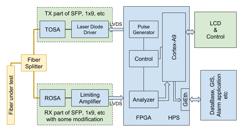
Here are some components, that are used in the device:

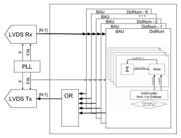
It should be noted that the main functions of our device can not be realized without using FPGA. Such functions as:
The ARM allowed us to show the results in the real time and we did it very easily.
The information below shows some main principles of work of OTDR. If you need more information, you should read JDSU, “Reference Guide to Fiber Optic Testing”.

A schematic diagram showing OTDR technology.
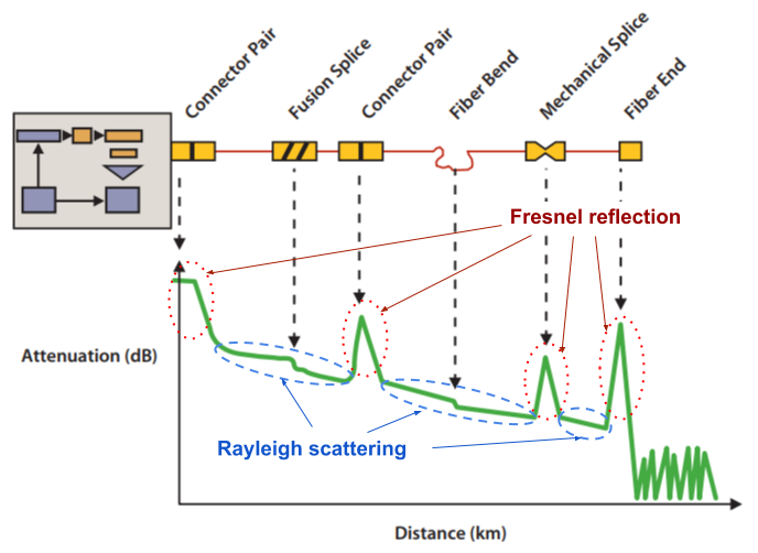
A typical OTDR trace.
Rayleigh Scattering: typical Rayleigh backscatter coefficient -80 dB (1ns pulse width). As result, the OTDR detector functions at extremely low optical power levels (as low as 100 photons per meter of fiber).
Fresnel Reflection: up to 4% (-14dB).
The following table provides the typical reflectance values for a fiber optic connection or break.
Glass-to-air -14 dB
PC-to-PC connector -35 to -50 dB
APC-to-APC connector -55 to -65 dB
In our project, we limit ourselves to registering Fresnel reflection from optical fiber defects.

TOSA - transmitter optical sub-assembly. The TOSA consists of a laser diode and monitor photodiode.
ROSA - receiver optical sub-assembly. The ROSA consists of a photodiode and Transimpedance Amplifier.

A typical schematic SFP (receiving path).
Contain Transimpedance Amplifier (TIA - ADN2880) and Limiting Post Amplifier (LA - ADN2890)
The voltage amplifier stage provides gain and converts the single-ended input to differential outputs. The DC cancellation circuit uses low-frequency feedback to remove the DC component of the input signal. This feature centers the input signal within the transimpedance amplifier’s linear range. As result this combination looks like 1-bit ADC for small signal.

xi = 1 or 0 => σ < 1
σmean = σ / √N < 1 / √N
Usually this technique is called oversampling.
Johann Carl Friedrich Gauss was born on 30 April 1777 in Brunswick (Braunschweig), in the Duchy of Brunswick-Wolfenbüttel (now part of Lower Saxony, Germany), to poor, working-class parents...
 Cut.png)