AP028 » Attitude and Heading Reference Systems Coprocessor using Madgwick’s Algorithm
We proposed an Attitude and Heading Reference Systems (AHRS) coprocessor from
tri-axis Magnetic, Angular Rate, and Gravity (MARG) and Inertial measurement Unit (IMU) sensor using Madgwick’s
AHRS sensor fusion algorithm. By relieving processor-intensive tasks from the
primary processor, coprocessors can accelerate overall system performance.
Orientation estimation is complex and extensive algorithm however it is used for many AHRS (Attitude and Heading Reference Systems) applications such as smartphone, UAV, robotic, and gaming console. The problem arises when implementing orientation estimation algorithm in primary processor. Orientation estimation algorithm will overload primary processor therefore it will be interfering another task that should be executed by primary processor. In this project, we proposed an AHRS coprocessor from tri-axis MARG (Magnetic, Angular Rate, and Gravity) or IMU (Inertia Measurement Unit) sensor using Madgwick’s AHRS sensor fusion algorithm. By relieving processor-intensive tasks from the primary processor, coprocessors can accelerate system performance and expected to prolong battery life.
AHRS coprocessor intended to be used as IP block in hardware block design and relieving orientation estimation task from soft processor or hard processor. AHRS processor require measurement data from MARG or IMU sensor that has been converted to actual values. The actual value is used for algorithm input parameter to calculates orientation estimation in quaternion representation or Euler representation.
AHRS coprocessor is not a new technology. There is some manufacturer that have been implementing this coprocessor in their product, such as Apple Inc. and Invensense. Apple Inc. implements their AHRS coprocessor using two approaches. The first approach is implementing AHRS coprocessor in NXP LPC1800 based microcontroller which can be found in M7 and M8 Apple coprocessor. The second approach is embedding AHRS coprocessor with main processor which can be found in M9 until M11 Apple coprocessor. In other hand, the AHRS coprocessor in Invensense product is embedded alongside with IMU sensor or MARG sensor. Unfortunately, all coprocessors mentioned before are closed source hardware since only the manufacturer knows the secret inside. Therefore, it can not be developed by the user community.
There are many researches about orientation estimation algorithm for example complementary filter, Extended Kalman filter, and Madgwick’s algorithm. Usually, this algorithm is implemented in microcontroller or microprocessor. Actually, these algorithms also can be implemented in FPGA which is better than microcontroller or microprocessor. However recent researches about implementing that algorithm in hardware design especially in FPGA, do not always accompanied by detailed source codes. Consequently, user community can not recreate it easily.
Table 1 Comparison of AHRS algorithm implementation in various hardware
|
Open source microcontroller or microprocessor |
Close source AHRS coprocessor |
Open source FPGA coprocessor |
|
|
AHRS algorithm can be updated after release to the market. |
yes | no | yes |
|
Compatible with various MARG and IMU sensor IC. |
yes | no | yes |
|
It can be design in parallel architecture. |
no | unknown | yes |
|
It can be developed by user Community. |
yes | no | yes |
Based on this problem, we offer a solution to make an implementation of AHRS coprocessor in FPGA based on open source hardware so thaht the user community could give feedback and support the development of these coprocessor. The development of this project posted in here.
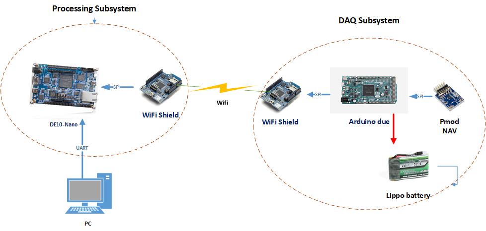
As mentioned before, this project has two separated subsystems, DAQ (Data Acquisition) and processing subsystem, as depicted in Figure 1. The DAQ subsystem consist of Arduino board, arduino WiFi shield, Pmod NAV, and lippo battery pack. The DAQ subsystem used for reading measurements from Pmod NAV then convert it to actual values. Then, the actual values are transmitted to processing subsystem using WiFi. The processing subsystem consist of DE10-Nano Kit and Arduino WiFi shield. The processing subsystem used for receive actual measurement value and implementing Madgwick’s Algorithm as hardware coprocessor.
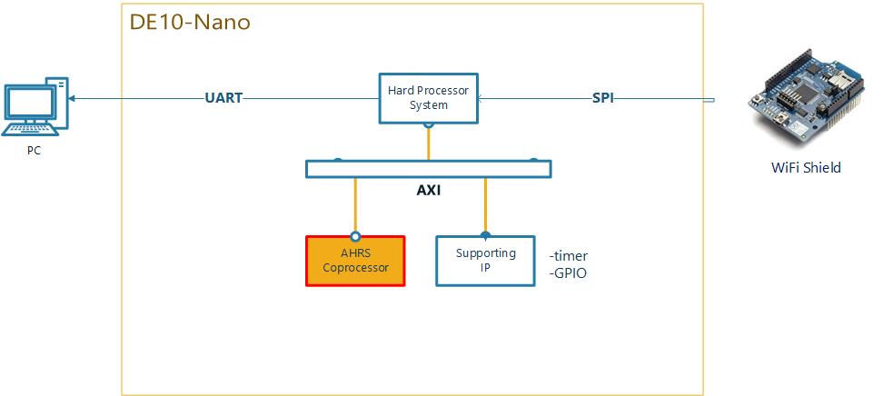
Hardware block design inside DE10-Nano Kit as described in Figure 2. It consists of hard processor system that has interfaces with several IP blocks and AHRS coprocessor using AXI interconnect protocol. First, Arduino WiFi shield receive actual data from DAQ subsystem. The received data is read by hard processor system then is sent to the an AHRS coprocessor. simultaneously, timer block IP start to run. It is used for determining AHRS coprocessor execution time. Next, AHRS coprocessor calculate the estimation orientation in quaternion representation or Euler representation. Then, the AHRS coprocessor send back the output data to hard processor system and stop timer block IP. Finally, hard processor system send the data to the PC via UART for performance analyzing.
In this project, we proposed an AHRS coprocessor using Madgwick’s AHRS sensor fusion algorithm. The algorithm uses a quaternion representation, allowing accelerometer and magnetometer data to be used in an analytically derived and optimize gradient-descent algorithm to compute the direction of the gyroscope measurement error as a quaternion derivative. The benefits of algorithm include: (1) computationally inexpensive 277 scalar arithmetic operations each update, (2) effective at low sampling rates; e.g. 10 Hz, and (3) contains two adjustable parameters defined by observable system characteristics. The AHRS coprocessor is expected to prolong battery life and increase systems performance due to coprocessor which calculate AHRS calculation task.
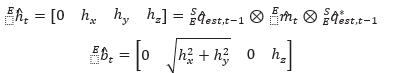
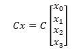
This algorithm work for IMU and MARG sensor. These two approaches are described in Figure 3. From the algorithm block diagram, we can divide block diagram into four main parts which are part A, part B, part C, and part D. For IMU and MARG algorithm block diagram, part B, part C and part D are similar. Part A in MARG algorithm block diagram has an additional input parameter from magnetometer. Part A task is estimating orientation from a homogenous field. Part B task is calculating quaternion derivative from quaternion multiplication of previous orientation estimation quaternion and current gyroscope actual data. Part C task is calculating estimated orientation rate of change form fusion process of part B output and part A output to compensate gyroscope integral drift. Part D task is calculating integration of estimated orientation rate of change and normalized it. Because part A and part B do not have dependency each other, it can be designed in parallel architecture as depicted in figure 4.
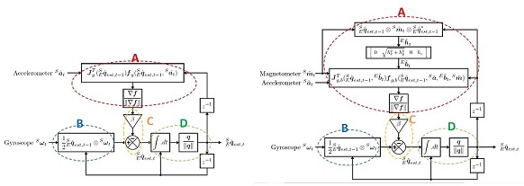
Figure 3 Block diagram of Madgwick's algorithm for IMU (left) and MARG (right) sensor
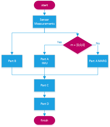
Figure 4 Algorithm fusion with MARG and IMU sensor
Partition is breaking the function into discrete smaller subfunction that can be distributed to multiple tasks. Madgwick Algorithm should be partitioned to smaller subfunction to able run in parallel. These subfunction are :
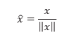
1. Normalize
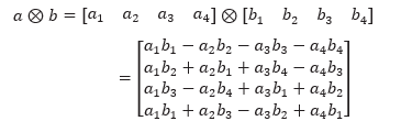
2. Quaternion multiplication
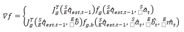
3. Objective function error
4. Reference direction of Earth's magnetic field
5. Multiplication of constanta and vector
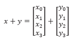
6. Addition of two vectors
This project using HLS procedure to generate HDL from the Madgwick algorithm that written in C/C++ language. The implemenataion of algorithm could be seen here.
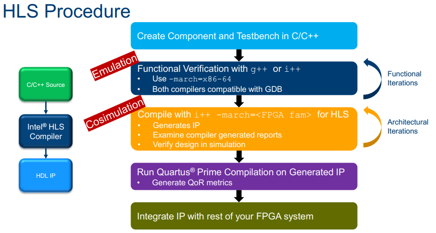
Figure 5. High Level Synthesis Procedure
the output from algorithm C/C++ simulation is compared with actual output of AHRS coprocessor to clarify the accuracy.
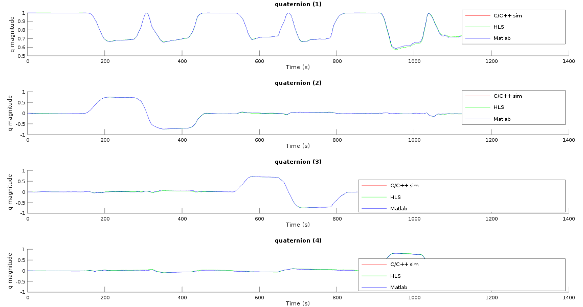
Figure 6. Quaternion Representation
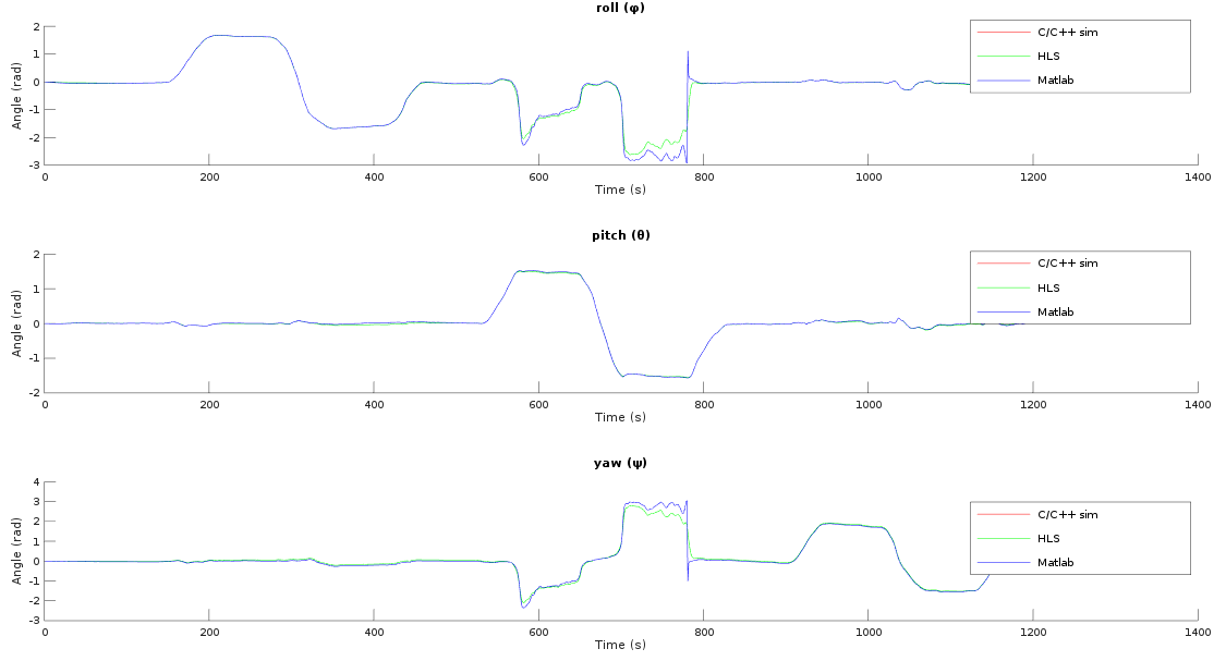
Figure 7. Euler Representation
*As the project is incomplete, the actual performance parameters data was unable to obtained. This data obtaied from another development board.
This project require several hardwares to run properly. The projet hardware are :
This development board is used for main part of processor subsystem. The Madgwick algorithm design is implemented in SOC inside this board.
SD card used for data logger.
This module is connected to DE10-Nano and used for receiving data from DAQ subsytem.
This board is the main part of DAQ sub system. It is used for transmitting data from Pmod NAV to processor subsystem.
Pmod NAV consist of 9 axis gyroscope, accelerometer, and magnetometer.
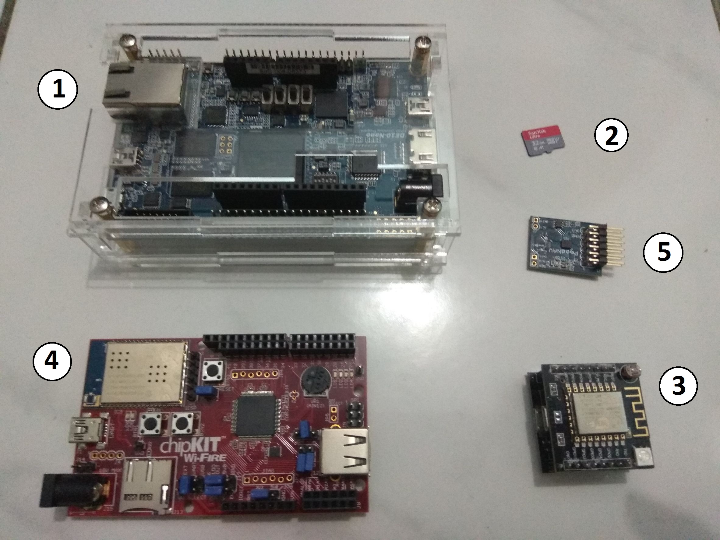 Figure 6. Hardware requirements