
AS043 » Quantum Gate Emulator
Our goal is to utilize an FPGA to create a high-speed quantum gate emulator directly in hardware, and couple this with a user-friendly interactive GUI accessible through a web server based application, which will allow the user to create circuits out of the emulated quantum gates using portable devices such as smartphones and laptops. With this project, we will create a viable environment for everyone from experts to students to create new quantum computing applications based on quantum gates, which will accelerate the advancement of quantum computers.
Quantum computing is a fast-growing area of interest in the computing world, as quantum computers are theorized to be able to solve problems much faster than classic computers. However, very few people have intimate knowledge of quantum computing, and the learning curve of understanding quantum computing is very high.
Our emulator is an “ideal emulator”. The emulator was designed with the mindset that it should be used as a learning tool for those who are beginning to learn quantum computing. Rather than overwhelming the user with all of the complexities and advanced topics of quantum computing, the emulator features a simple display and a simple sandbox for experimenting with different gates. The emulation features the most fundamental quantum gates and does not consider certain physical properties of quantum bits, such as entanglement.
The emulator consists of three main components:
The web app which constitutes the user interface
A web server, written in Python using Flask, which utilizes precompiled C executables to interact with the FPGA fabric
The actual quantum gate emulation circuit written in VHDL and programmed for the DE10-nano
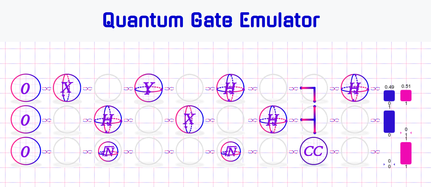
The web app is the user interface for the emulation. The web app displays a small sandbox for the user where the user is able to change the initial states of the qubits, add and remove gates from the circuit, and view the final output. The final output is represented as the probability of measuring different states.
The web server runs on the ARM Cortex A9 processor on the DE10-nano SoC. The server is accessible through the local network of the board. The server reacts to changes the user makes to the emulation through the web app and invokes executables, written in C, to communicate with the FPGA and update the emulation.
The emulation runs in the FPGA fabric of the DE10-nano. The emulation utilizes combinational logic to perform operations on the input qubits in a pipelined architecture. The emulation is “programmable” at runtime; the circuit has been designed with parallel I/O signals which control the selection of gates at each stage of the pipeline.
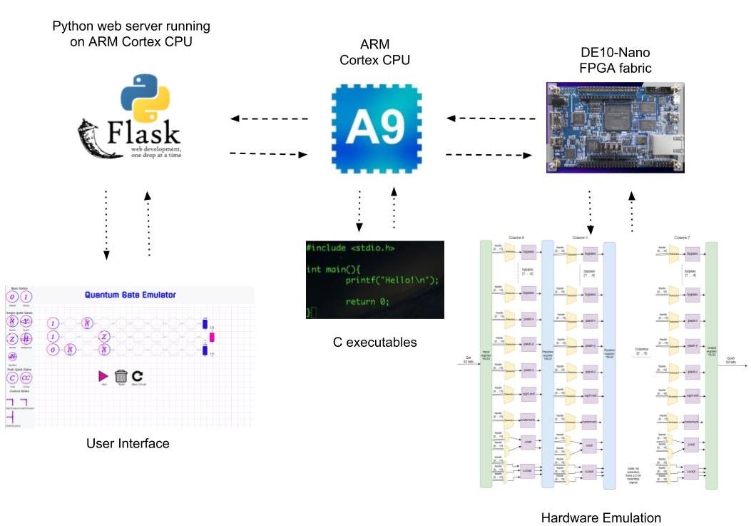
Figure 1 -
High-Level block diagram of the system. The Python web server hosts and communicates with the web app, and this server runs on the on-board ARM Cortex CPU. The CPU is also able to invoke C executables in order to communicate with the FPGA fabric where the emulation is run and implemented.
The three inherent virtues of FPGAs are:
Boosted performance
Adaptable to change
Expansion of I/O
This design demonstrates the “Boosted performance” and “Adaptable to change” FPGA virtues.
Boost Performance:
The emulation of the user-created quantum circuits is done entirely on the FPGA. Because this task was off-loaded from the CPU, the CPU was free to perform other work. In this case, this means that the CPU is capable of hosting a web server and communicating with the FPGA at runtime.
In addition, the circuit is programmable at runtime. This means that all changes the user makes to the circuit are updated immediately, and the output will always be ready whenever the user clicks the button to obtain the final qubit states. This level of performance would not be possible with a software simulation.
Adapt to change:
The design is extremely scalable. The emulation is addressed using a specific bit format:
<1cccrrrr> where “ccc” is for addressing the columns of the pipeline and “rrrr” is for addressing rows. This allows 8 columns to constitute the pipeline and 16 rows in each level of the pipeline. Each row is a quantum gate, and thus this design can implement up to 13 unique quantum gates. Adding additional gates and columns would simply require additional address bits, and because the web server communicates with the FPGA through 32-bit signals, scaling up the design would be very simple.
Our project’s goal was to allow beginners to the field of quantum computing the chance to experiment and learn with simple quantum circuit emulations. The application can be used as a learning tool for any educational institution to allow its students to easily build quantum circuits. People of any education level can use this tool, as its learning curve is very low, while still allowing knowledgeable users to interpret its results. Intel FPGA’s were essential to the creation of this project, as we needed a SoC that combined a powerful microprocessor like the dual-core Cortex-A9 with efficient FPGA fabric, as well as the ability to seamlessly communicate between the two. This high performance, but low-powered device could be used by any educational center to provide a cost-effective way to allow anyone to learn about quantum gates.
The project consists of three main components: The website/user interface, the HPS-FPGA communication, and the quantum circuit emulation on the FPGA.
The web app is written completely in HTML and Javascript. The decision to use these web technologies versus other implementations was two-fold. Firstly, we wanted our project to be as portable as possible. By using these two technologies, we allow any web connected device with an internet browser to be able to access and use our circuit. Secondly, by using HTML and Javascript, we allow for easier customization, and future expansion due the lower level of difficulty when working with these technologies. While these languages are easy to use, no sacrifices to ease-of-use of the application have been made when building the web app. To allow for people of all skill levels to be able to use and understand the project, a simple drag and drop circuit was created, where all start states, and quantum gates can be either dragged onto the circuit, or dragged into the ‘trash’. To further aid beginners, we only allow valid, logical actions to be taken with the circuit, so that users are not left with a non-functional quantum circuit after they take incorrect actions.
The visual design of the website was carefully chosen so as to appeal to users of all skill levels. The gates are represented with visual motion that conveys the actual characteristics of the gates, and all gates in our circuit are also accompanied by a short description of their properties. The output of the web app is an easy to understand, yet completely theoretically accurate probability chart of measuring a qubit state of zero or one
The operation of the UI is simple, start states of the circuit are dragged into the designated column, and all other single and multi qubit gates are dragged into the body of the circuit. Checks are performed whenever a user performs and action to ensure for proper circuit structure. When the user wants to see the output of their circuit, they simply click the play button. Additional functionality is provided with a ‘trash can’ where users can drag their unwanted gates, and a ‘new circuit’ button to remove all gates.
The quantum gate emulation was designed and implemented in the FPGA using VHDL. The circuit is essentially a programmable gate array consisting of 8 columns of 13 gates each. The 8 columns are preceded and followed by a pipeline register. There are 11 single input gates: 6 bypasses, and 1 each of the Pauli-X, Pauli-Y, Pauli-Z, Square-Root of Not, and Hadamard gates, and 2 multi-input gates: the two-input CNOT gate and the three input CCNOT or Toffoli gate. This makes for a total of 16 inputs and 16 outputs to the main circuit. Additionally, each gate in each stage of the pipeline has a selecting multiplexer before it to allow the C executables to choose the input to the gate from the previous stage’s output register. Using these muxes, the circuit can be “programmed” to match the circuit created by user of the web app.
The HPS-FPGA (Hard Processor System) communication is implemented in the web server as well as in the FPGA. The web server, which is written in Python using Flask, runs on the ARM Cortex A9 processor on the DE10-nano board. The web server hosts the website on the local network that the DE10-nano is connected to via ethernet cable. The web server responds to the changes in the state of the emulation that are caused by the user interacting with the webpage via HTTP POST and GET commands. The possible actions that the user can take, and thus the actions that the web server must respond to, are:
Changing the initial state of the input qubits
“Running” the emulation in order to obtain the output qubit states
Removing a gate from the emulation
Adding a gate to the emulation
Initializing the simulation
All of these actions that the user can take involve communicating with the FPGA because the emulation runs on the FPGA. In order to allow communication between the FPGA and HPS, Parallel I/O (PIO) signals were added to the quantum emulation in VHDL. These PIO signals, which were created using the Qsys tool in the Quartus II software, are connected to a separate higher level circuit that was designed specifically for handling the communication between external signals and the combinational quantum circuit emulation. The circuit is responsible for basic read and write operations. “Reading” corresponds to obtaining the final states of the qubits at the output stage of the pipeline. “Writing” corresponds to modifying the selection signals in the quantum emulation, which allows the user to select different gates at each pipeline stage. Writing also allows the user to change the initial states of the qubits at the input stage of the pipeline.
The communication circuit is sequential and utilizes two GPIO registers, one for reading and one for writing. Each GPIO register is connected to an external signal, generated in Qsys, that allows for communication with the on-board processor. Also connected to the circuit are read and write enable signals. In order to program the emulation, the user must enact two sequential write operations. The first write operation selects the data register to write to, and the second write operation writes a value to the previously selected data register. The quantum emulation has 256 data registers, and so this design choice makes sense because it allows the user to address 256 separate data registers with only a single input signal. Reading a value is also a similar process; the user writes to the input signal the address of the output stage to read, and the output signal is then set to be the value of the output stage at the specified address.
C programs were then written to be able to read and write values to these external signals. These programs access the FPGA peripheral memory map and read/write values to and from these memory locations which correspond to the external signals of the emulation. In order to allow the web server this functionality, general purpose C executables were created that the server can invoke. Three generic C executables were created for this purpose: “write_gate”, “write_input”, and “read_output”. These executables accept input arguments so that the web server can address specific gates and input/output registers in the emulation to read and write. The web server invokes these executables depending on the actions taken by the user, and this programs the quantum emulation in real-time.
The main performance metric considered in this design is the speed of the emulation. Because the emulation is presented in a web app, there will be some delay due to the networking aspect, but because the website is only hosted on the local network, this delay is minimal. In addition, the emulation is updated with every action that the user takes. This means that when the user requests to view the output of the circuit, there is no delay in obtaining the output.
The main goal of the design is to serve as a learning tool for beginners to quantum computing. The emulation was designed to be an “ideal” emulation that does not take certain physical factors into account, such as noise or entanglement. The user interface of the simulation was also designed to be very simple and easy to understand for those who are just starting to learn about quantum computing. The output of the emulation, as displayed in the web app, is a simple bar graph showing the probability of measuring the different qubit states.
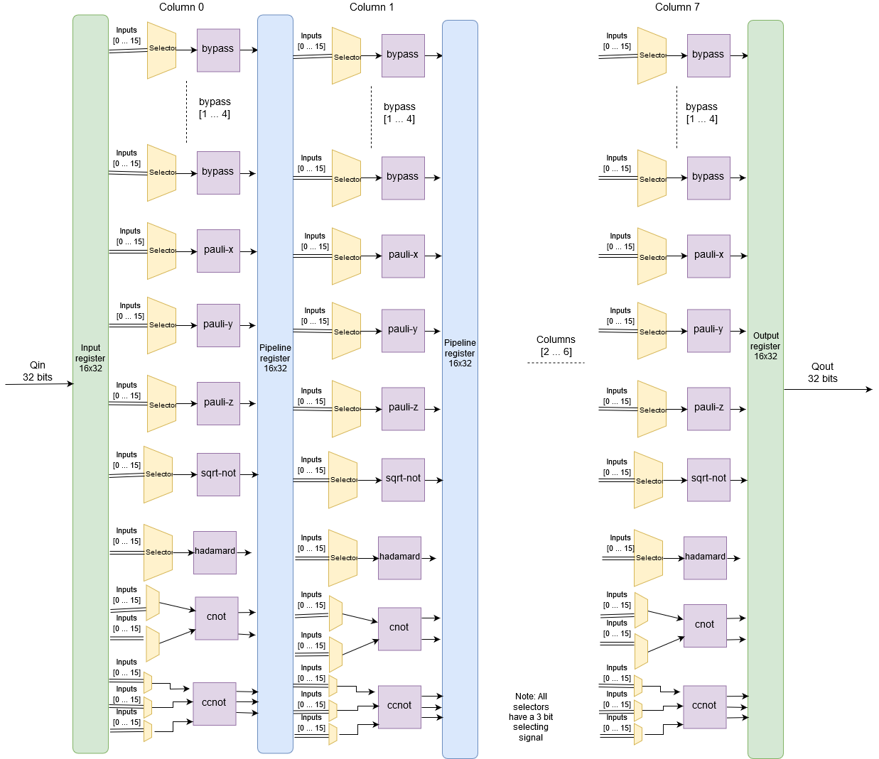
Figure 2 -
Block diagram of the Quantum Gate Emulation, written in VHDL and implemented in the FPGA of the DE10-nano. The circuit is combinational and utilizes a pipeline architecture, as depicted above. Each pipeline stage has 16 input and 16 output signals, where each of these signals corresponds to an input/output of a quantum gate.
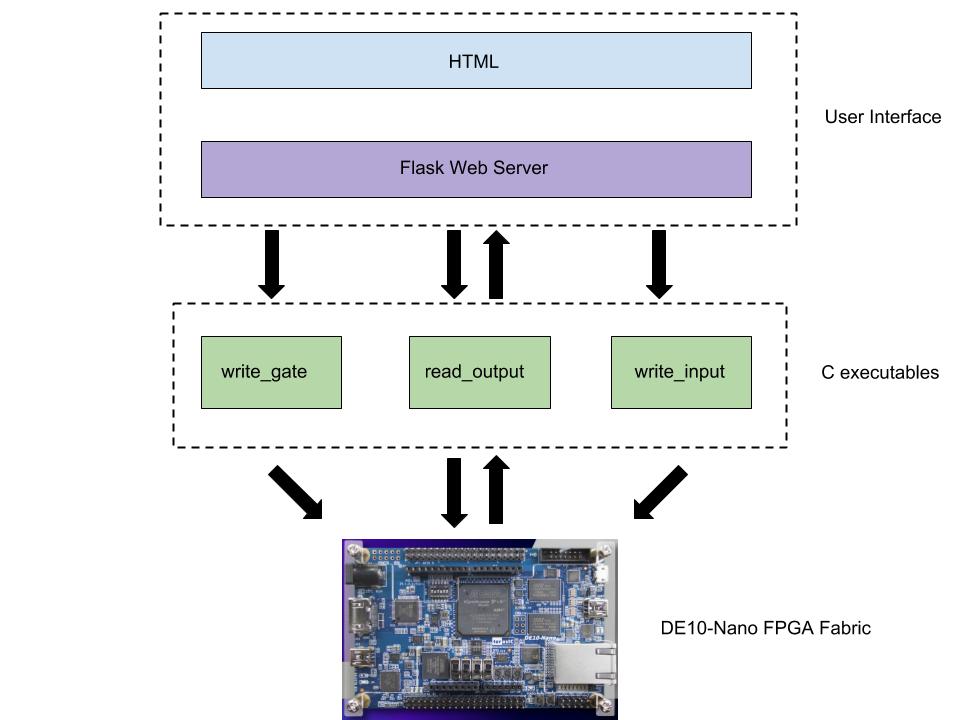
Figure 3 -
Software flow diagram of the system. The User Interface is made up by our web app, which was designed using HTML and a Python web server using the Flask framework. The web server invokes C executables in order to communicate with the hardware emulation running in the FPGA fabric of the DE10-nano.
From the beginning, the system was designed with the idea that the emulation will be “ideal” and that it should be a simple, user-friendly tool for those beginning to learn about quantum computing.
The first consideration made was the representation of a qubit. A qubit is represented by two probabilities, α and β, both of which can be complex numbers. Because these are probabilities, the values must be in the range [0, 1]. A fixed point representation was chosen to represent each probability, and in this representation, the MSB has a weight of 20 and every subsequent bit has a weight equal to a decreasing power of 2. The qubit was chosen to be represented by a single 32-bit signal to simplify read/write operations, and so α and β are 16 bits each. Because both of these probabilities are complex numbers, the real and imaginary parts of these numbers are 8 bits each.
Each of the emulated gates were programmed in a VHDL package with combinational logic. A procedure was written for each gate to operate on the qubit probabilities using the gate’s characteristic matrix. Matrix multiplication and complex arithmetic was used to determine the correct mapping of the input real and imaginary parts of α and β to their result. For the two multi-input gates (CNOT and CCNOT), the state of the controlling qubits had to be determined within the circuit. A pseudo-random number generated by LFSR in the higher level communication circuit was checked against the controlling qubits probability. Following the principles of quantum mechanics, once the qubit’s state was observed, it’s probability of being in the observed state was updated to reflect the certainty of it being in that state.
The emulation was designed to be “ideal” in that it ignores certain physical phenomena associated with quantum computing such as noise and entanglement. Ignoring these factors makes the emulation simpler and more easily understood by beginners. The emulation was designed with a pipelined architecture so that it could be programmable at runtime. Each stage of the pipeline has multiplexers for each gate so that gate I/O signals can be routed to different gates at each pipeline stage. Finally, the quantum gates were designed to be combinational so that they could be easily integrated with the pipelined emulation. Because the architecture of the emulation is pipelined, the output of each gate needs to be observed in one clock cycle.
In the emulation, there are 256 data registers, where registers 0 to 15 are associated with input qubits and registers 127 to 255 are associated with the select signals for the multiplexers at each pipeline stage. In order to limit the number of external signals to the emulation, one general-purpose input signal and one general-purpose output signal are connected to the high-level communication circuit described previously.
The web app was designed to have a simple UI so that those who lack knowledge of quantum computing can easily experiment with different gates and observe their outputs. Hovering the cursor over a gate will display a quick description of the gate’s function so that beginners can learn about the uses of different quantum gates. The output of the emulation was chosen to be a simple bar graph representation of the qubit probabilities which is easily understood.