

EM097 » FPGA-based Autonomous Vehicle Control System Design
In Ethiopia, the number of deaths due to traffic accidents is reported to be amongst the highest in the world. According to the WHO, in 2013 the road crash fatality rate in Ethiopia was 4984.3 deaths per 100,000 vehicles per year, compared to 574 across sub-Saharan African countries. In general, the scale and the severity of the problem are increasing from time to time and adversely affecting the economy of the country in general and the livelihood of individuals in particular.
I propose to design and implement motion speed control and relative distance measurement for vehicle. The system will have object detection, distance measurement and motion control. The car can detect objects and measure distance to that object. Thus the speed of the car is controlled according to the relative distance measured. The relative distance is measured using Stereo Vision Technology. The system can permit to control the car directly by using commands that are sent using keyboard.
To design a model that limit speed exceeding safe conditions, such as the speed for which the road was designed.
To show for the driver the distance of car to nearby car or any other object.
To emphasize that use of FPGA to control road traffic accident
To demonstrate the feasibility of the approach using FPGA
To control directly the real vehicle using control commands that are sent using a keyboard.
Applications: the scope of this project is limited to autonomous vehicles. But blind people can use to detect nearby obstacles and measured relative distance and take an action with some simple modification on the system design.
Target User: the product is used to control autonomous vehicles. Peoples who has cars can use it and blind peoples can use to navigate their environment.
Methodology
In my proposed method, to avoid road traffic accident. I have design a model that implement and control the speed of car.
A first step implements an object detection(not completed), to testify if that whether car or some other object is present. If there is object, the car will measure the distance to that object. As the car moves and closes to the object the distance will be gradually decreased hence the speed of the car must be also decreased by some factor. The speed controller model is going to take an action in accordance to the measured distance. The relative distance is going to be measured using Stereo Vision Technology. As the world progresses towards human comfort and automation, depth perception forms an integral part of automated navigation and motion. There are several techniques that are implemented for the purpose of obstacle detection and distance perception. Some popular methods include use of infrared sensors, ultrasonic sensors, common RADAR technology, a combination of digital camera and Laser, etc. Most of these methods involve recording of time between transmission and receiving of the signal. Other systems may use Laser stripping, optical flow, etc. However, the sensors used in these methods are very strongly affected by environmental conditions like temperature, fog etc. Also, these methods provide information only about the distance of the object and not its geometry. The image sensor that I use, i.e. the camera is less affected by environmental parameters and provides information about the geometry of the object too which can be further utilized for navigation and other such purposes.
The second step is to design and model a car speed controller system that controls the speed of the car(not completed). This model controls its speed according to the distance measurement and speed limited by the road design. So, the system model takes a distance measurement and maximum allowed speed while the car is driven to that road. The designed system will attenuates the speed of the car as the car closes to another car or object which is moving infant of it. Otherwise the car will be driven by maximum allowed speed. According to the rule, the maximum speed limit when driving on the city’s main roads will 50km/h and 30kmh around hospital, religious institutions, schools, market and related public places.
The car control system is developed in a microcontroller i.e. HPS (Hard Processor System) with several peripheral embedded in a Field Programmable Gate Array (FPGA). The embedded ARM-included DE1-SoC development board implements the main control of car tasks in software functions, namely: brake, clutch, steering wheel, gear and throttle subsystems of a real vehicle. Each function will have written in C language in a structured software approach.The Altera SoC EDS software tool is an embedded development environment that includes a library of peripheral IP cores used for intuitive hardware system creation. Additionally, a Built On Eclipse software development environment, GNU compiler and a debugger are also included.
The third step implement a display action. The speed of car and measured distance is going to be displayed to driver. I am going to use LCD screen to display speed and distance.
Additionally, keyboard is going to be used to control directly the real vehicle. The control commands are sent using a keyboard. The communication between the FPGA-based control system and the car is accomplished through an electronic module, which comprises several insulating and power circuit boards. The virtual instrumentation approach (for simulation and controller design objectives) is used for implementing a high-level abstraction simulation environment in LabVIEW tool, which allows representing the movement of the car in real time. This approach opens a great variety of possibilities to validate and simulate solutions for several problems in robotic and mechatronic areas. The tests and initial overall system validation will accomplished in the simulator environment. Then, the simulation results will compared with the movement variables of the real car, which will gathered in real time. This approach makes possible to test and to validate the control system with low cost and more safety.
Block Diagram
A. System Block Diagram
Figure 1. The Overall System Architecture
B. System Flow Diagram
Figure 2. Flow Diagram of the embedded system
Intel FPGA Virtues in My Project
Processors and FPGAs (field-programmable gate arrays) are the hardworking cores of most embedded systems. Integrating the high-level management functionality of processors and the stringent, real-time operations, extreme data processing, or interface functions of an FPGA (Field Programmable Gate Array) into a single device forms an even more powerful embedded computing platform.
SoC FPGA devices integrate both processor and FPGA architectures into a single device. Consequently, they provide higher integration, lower power, smaller board size, and higher bandwidth communication between the processor and FPGA. They also include a rich set of peripherals, on-chip memory, an FPGA-style logic array, and high speed transceivers.
SoC FPGA advantages
• No expensive NRE charges or minimum purchase requirements, for a single, SoC FPGA, or millions of devices, cost-effectively.
• Faster time to market. Devices are available off-the-shelf
• Lower risk. The SoC FPGA can be reprogrammed at any time, even after shipping
• Adaptable to changing markets requirements and standards, supporting for in-field updates and upgrades
• No additional licensing or royalty payments required for the embedded processor, high-speed transceivers, or other advanced system technology.
FPGA devices have been used for automation and control system rapid prototyping and they make possible to develop high performance systems in short periods of time. Besides, it is possible to have a smaller number of devices at reasonable costs. The term SoC (System on Chip) and has been widely used in automation/control system design, communications systems, among others, which involves the use or implementation of different IPs (Intellectual Properties), and a full integration on the FPGA component.The structure of SoC devices with FPGA is fully flexible and can easily respond to changes in the control system logic. The capability of modifying the logic enables the control system to implement future additions with ease.
Stereo vision and object detection is implemented, the object detection testify that whether object is present. If there is object, the car will measure the distance to that object. As the car moves and closes to the object the speed of the vehicle will decreased by some factor. The relative distance is measured using Stereo Vision Technology. The speed controller model takes an action according to the object detection and stereo vision.
The Design of the FPGA is made up of main components: the OV7670 camera, the Altera DE10-Nano development board Cyclone® V SE 5CSEBA6U23I7 , Geared Dc motors and L293D motor driver.
Stereo vision uses two adjacent cameras to create a 3D image of the world. A depth map can be created by comparing the offset of the corresponding pixels from the two cameras. However, for real-time stereo vision, the image data needs to be processed at a reasonable frame rate. Real-time stereo vision allows for mobile robots to more easily navigate terrain and interact with objects by providing both the images from the cameras and the depth of the objects. Fortunately, the image processing can be parallelized in order to increase the processing speed. Field-programmable gate arrays (FPGAs) are highly parallelizable and lend themselves well to this problem.
Physical Overview
4.1 Camera and FPGA Development Kit
The OV7670 image sensor and DSP module is a low cost CMOS device that is capable of processing VGA resolution images (640x480) at 30 frames per second . A large number of registers must be configured via the Serial Camera Control Interface (SCCB) to select the processed image resolution, output data format and other parameters related to the image quality. This SCCB interface is compatible with the industry standard I2C protocol.
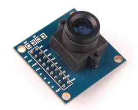
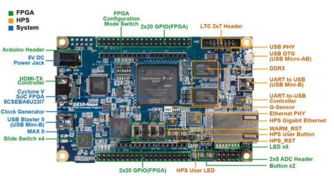
Figure1.1 OV7670 Camera Modul Figure1.2: DE10-Nano development board
4.2 Display
The development board provides High Performance HDMI Transmitter via the Analog Devices ADV7513 which incorporates HDMI v1.4 features, including 3D video support, and 165 MHz supports all video formats up to 1080p and UXGA. The ADV7513 is controlled via a serial I2C bus interface, which is connected to pins on the Cyclone V SoC FPGA.
4.3 Setup/ Connections
Setup and operation of the FPGA face detection system is rather simple. Assuming the DE0-Nano development kit is used, a 5V 2A power source is required. The VHDL code needs to be synthesized using Quartus Prime 17.1 software and programed onto the FPGA. A HDMI cable connects the board to a generic VGA monitor port and the camera is connected to the necessary GPIO pins. The motor driver is connected to necessary GPIO pins and geared dc motor. The setup should look similar to figure Any display issues can be fixed using the reset switches (SW[1] and SW[2]).
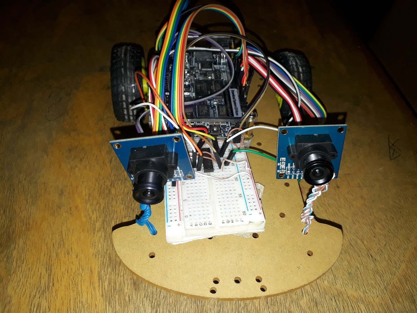
Figure1.3 Physical System Design Overview
5 Top Level Design
The top level of the design consists of a number of components. These components facilitate image frame capture, processing and display. All of these top-level components are synchronized and controlled from a top-level control unit. A phase lock loop (PLL) generates clock signals that are distributed to each component for synchronous processing of the subsystems. Details on each top-level component are discussed in the following sections.
5.1 Camera Driver
The camera interface consists of two components. This includes the OV7670 Controller module and the OV7670 Capture module. The OV7670 Controller configures registers on the camera via I2C, writing the configuration data sequentially to the camera. The OV7670 Capture module effectively captures and formats data that is received from the camera. 320x240 images are captured at 30Hz into the image frame buffer with a data format of 12 bit color (RGB 4:4:4). It should also be noted that the register configuration for the OV7670 image sensor is poorly documented, so it was extremely beneficial to use working register values from.
5.2 HDMI TX
HDMI transmitter to generate video pattern and audio source. The entire reference is composed video design and I2C design. A set of built-in video pattern will be sent to the HDMI transmitter to drive the HDMI display.
5.3 Memory Architecture
A single image frame buffer is utilized for storing captured frames from the two cameras. This buffer has 76,800 addressable memory locations to store a 12-bit color image with a resolution of 320x240. Two buffers are implemented in the design to enable high bandwidth memory reads from both right and left image frame buffer for stereo vision and object detection. Since multiple processes, operating at multiple clock frequencies, write to or read from this buffer, a number of multiplexers switch the port addresses along with the read/write clocks.
The Left and right image frame buffer contains two frame buffers to store images that is read left image data from image frame buffer and processed image from stereo vision and object detection implementations. All the image frame buffer are generated using RAM-2 IP.
5.4 Stereo vision
Stereo vision uses multiple images of the same scene, taken from different perspectives, in order to construct a three-dimensional representation of the objects in the images. Comparing multiple images together for their similarities and differences allows for the depth to be obtained. By searching for corresponding pairs of pixels between the two images, depth information can be determined. Pixel based comparisons can require substantial amount of computational power and time. Certain assumptions are made because of the resources required. Camera calibration and epipolar lines are common assumptions. Camera calibration refers to the orientation of the cameras to each other. Epipolar lines are lines that can be drawn through both images that intersect corresponding points.
Sum of Absolute Differences (SAD) algorithm is implemented. SAD algorithm uses regions of pixels called windows to compare pixels to find matching pairs for determining depth. The implementations use a 5x5 window for comparison and is able to process 2 pixels simultaneously.
Images at a size of 320x240 pixels would require a quarter of the number of computations, but at the cost of losing detail of the objects in the images. Computational requirements for real-time applications can be reduced in several ways thus lowering the number of pixels in the images will reduce the number of pixel comparisons in each second and reducing the number of frames per second will decrease the amount of computing needed.
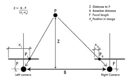
Figure3.1 : Stereo Vision System
The two cameras are held at a known fixed distance from each other and are used to triangulate the distance of different objects in the images they create. The points Left camera and Right camera, are 2D representations of the point P in 3D space. By comparing the offset between Left and Right camera in the images, it is possible to obtain the distance of point P from the cameras. The closer an object is to the stereo vision system, the greater the offset of corresponding pixels will be. If an object is too close to the system, it is possible for one camera to see part of an object that the other camera cannot. The farther an object is away from the stereo vision system, the smaller the offset of corresponding pixels. If an object is far enough away, it is possible for an object to be in almost the exact same location in both images. You can show this to yourself by holding a finger up close to your face, close one eye, and then alternate between which eye is open and which eye is closed. Your finger should appear to move a noticeable amount. Next, hold your finger as far away from you as you can and again alternate between which eye is open and which is closed. You should notice that your finger appears to move significantly less than it did when your finger was close to your face. That is how stereo vision works. The distance of an object is inversely proportional to the amount of offset between the two images.
5.4.1 Stereo Vision Algorithm
5.4.1.1 Sum of the Absolute Differences (SAD) Algorithm
SAD is a pixel-based matching method. Stereo vision uses this algorithm to compare a group of pixels called a window from one image with a window in another image to determine if the corresponding center pixels match. The SAD algorithm, takes the absolute difference between each pair of corresponding pixels and sums all of those values together to create a SAD value. SAD is a pixel-based matching method. Stereo vision uses this algorithm to compare a group of pixels called a window from one image with a window in another image to determine if the corresponding center pixels match. The SAD algorithm, takes the absolute difference between each pair of corresponding pixels and sums all of those values together to create a SAD value. Several SAD values will be calculated from different candidate windows for each reference window. Out of the all the SAD values calculated for the reference window, the SAD value with the smallest value (all of them are greater than or equal to 0 because of the absolute part in the equation)is determined to contain the matching pixel. The disparity is the amount of offset between two corresponding pixels.
5.4.1.2 Sum of the Absolute Differences Architecture
The SAD algorithm uses 5x5 window, it has a clocked input (clk_I) and a 1 bit data input (data I) to notify the algorithm to begin calculating the SAD value, 5x5 template window I and search window
The1 bit data out signal (data O) notifies when the calculation is complete and is ready for the next set of input. The calculated SAD value is sent out through sad O.
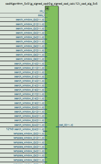
Figure 3.2 The top level SAD algorithm implementation
5.4.1.3 Minimum Comparator Architecture
The purpose of the minimum comparator is to find the lowest value of two input values and output the lowest value. The process is synchronous, noted by the clock clk I. The index, pos0 I and pos1 I, of the SAD values sad0 I and sad1 I, respectively, ranges from 0 to 15, which gives a disparity range of 16. If sad1 is less than sad0, then sad1 and its index, pos1, are returned, otherwise sad0 and pos0 are returned.
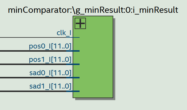
Figure: 3.3 The top level minimum comparator implementation
5.4.1.4 SAD TOP level controller
The SAD_Top is the entity that encompasses the SAD algorithms and minimum comparators. SAD_Top receives a clock signal through clk_I and a reset signal through rst_I. It gets the template image data through templ_I and receives the search image data through search I. The write t I and write s I notify the SAD_Top when new data is actively being sent from the template and search images, respectively. It is designed to allow data from both images to be sent to the SAD_Top.
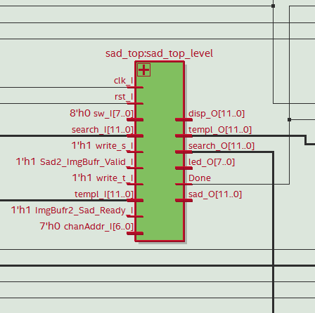
Figure3.4: SAD top level entity
5.5 Object detection
The problem of object detection is addressed by the implementation of Background Subtraction algorithm (BS). This algorithm uses the difference of the current video frame and a reference background frame for the detection of new object(s) in the scene. This algorithm has chosen due to its simplicity of implementation as opposed to others, which can bring some timing advantages to the project, as it proposes to work in real time. Evidently, such simplicity presents considerable disadvantages such as the poor robustness to noise, variations in the background and illumination conditions. Some measures, such as image filtering and thresholding, can be taken to minimize the effects of some of the disadvantages. Due to the lack of robustness of the algorithm, the project will be best suited for controlled environments in terms of illumination and movement. The BS algorithm will be applied to images captured from the OV7670 camera and stored in the RAM-2 of Left and Right frame buffer .The resulting data will be further processed for more accurate results and later displayed on the screen through HDMI-TX.
5.5.1 System Architecture
The system’s global operation can be divided in two main operations: image post-processing and image display.
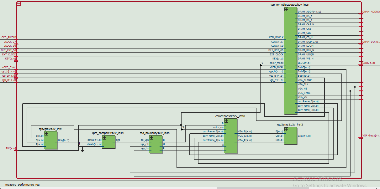
Figure3.5 : object detection top level entity
5.5.1.1 Image Post-Processing
After reading the image’s data from the RAM-2 of Left and Right image frame buffer, it will be converted RGB value using RGB converter block the absolute difference value between the reference background and the current frame for each pixel is calculated. the value of this threshold can be adjusted through the configuration. After binarization, a final component draws a red contour around white structures in the binarized image through a simple edge detection implementation.
5.5.1.2 Image Display
The displayed data depends on the selected threshold value for binarization and on the selected color mode. If the selected color mode is the binarized differences image, the binarized image and red contours obtained in the described image post-processing phase will be displayed. Otherwise, the original RGB object data and the same red contours will be displayed.
5.6 Motion Control
5.6.1 Motors
To move the mobile platform forward, backward, turn left right two 3-5V 170rpm geared motors are used. In order to operate the motors L293D motor driver was used. When a PWM pulse is supplied to the motor driver it controls the speed of the motors accordingly. There are two pins for each motor for direction control. The PWM signal should be fed into one pin while the other pin is LOW.
The PWM signal generation is done by the FPGA development board. For this two VHDL entities are needed. A clock divider entity and a PWM generation entity. The clock division is done by a counter. A counter which runs at 50MHz is used. The 6th bit of the counter is output as a clock to the PWM generation entity which has a period of 0.00256ms. Then the PWM entity sets the period and the duty cycle. The period is predefined to get a 2kHz wave.

Figure3.6: PWM Block Diagram
5.6.2 Motion Control
According to the VHDL program the FPGA chip takes input from the Stereo vision and convert the disparity to depth . it will also take inputs form object detection and detect objects. Then according to a rule base the movement of the motors are controlled in order to get away from the object and move forward according the distance measured . This distance is set as 20cm. Then according to the stereo vision and object detections the motors are operated. The PWM changes dynamically in order to get the desired movement.
6.1 Experiments and Results
The code used on the FPGA board was written in VHDL and Verilog . Disparity map images, testbench simulations, and counting clock cycles were used to compare the accuracy and speed of the VHDL implementations. The images were processed from top to bottom, left to right, where the column width was based on the number of pixels processed in parallel. To test for the maximum possible frames per second the SAD could perform at, clock cycle counting on the FPGA board and testbench simulations were used to obtain the time it should take to produce a disparity map on the board for a 50 MHz clock.
The state machine first enables new image frames to be captured into the image buffer and then proceeds to process the image. The two camera capture the images, the image frame buffer takes the images data and stored on the prospective place. The Left image data is stored on the port A and the right image data is stored on the port B. The left and right image frame buffers takes the image data and store on the port A of each image frame buffers. This image frame buffer has two port to store the captured image data and processed image data from either stereo vision or object detection block. when the camera captures image and store on the image frame buffer an LED will blink to notify the status of the work.
The size of the window affected the quality of the disparity map and the number of computations required to create the disparity map. The 5x5 window size is used, each SAD calculation only had 25 pairs of pixels to process. they provided a good compromise on the amount of noise in the disparity maps to the amount of hardware resources required for implementation.
The objects are successfully detected. There’s still some noise in the image but quite reduced.
Several objects are placed on the road map. The robotic vehicle detects the object and measured distance using the stereo vision. The motors are governed according to the object detection and stereo vision. When the object is detected and reached 20 cm a head, the robotic vehicle was turning to the right direction for which there is no object. The object has got mis conceptions and moving to undesired place , this is due to the fact that the object detection and stereo vision generating bad result . The algorithm presents some limitations, leading to undesirable results under certain conditions.
i have tried to display the disparity map and detected image using the HDMI output port on the screen, but i doesn't work well. The HDMI ouputs a disruptive signal or no signal.
6.2 Conclusions
For image processing, the more operations that can be parallelized, the faster an image can be processed. However, as parallelism is increased, the amount of hardware required is also increased. It could be possible to parallelize a SAD algorithm to the point where it only takes a few clock cycles to process the whole image (i.e. every SAD calculation for an image pair occurring simultaneously).
The hardware cost to obtain the higher levels of FPGAs would be very cost prohibitive and not something a club or hobbyist could readily use for this project. There does come a point where the frames per second of disparity maps exceeds the rate the other parts of the robotic vehicle can process, which is an unnecessary cost. So the FPGA board only needs to be able to handle a SAD implementation up to a certain frame rate and image quality.
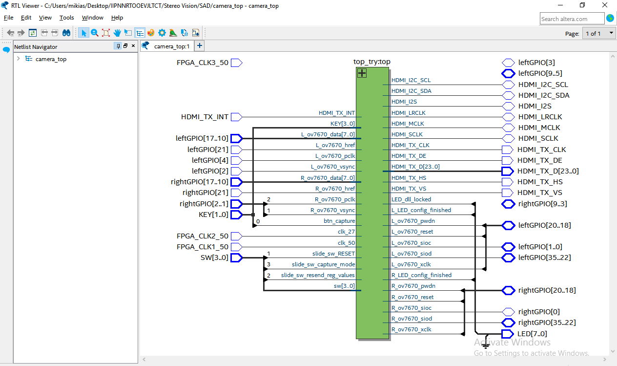
Figure7.1 : Top level design
FPGA Virtue
Processing images for stereo vision allows for a high degree of parallelism. Locating the corresponding position of a pair of pixels is independent of finding another corresponding pair of pixels. This independence allows for the ability to process different parts of the same images at the same time, as long as there is hardware to support it.Field programmable gate arrays (FPGAs) allow for a higher degree of parallel .
8 Reference
[1] http://www.sciencedirect.com/science/article/pii/S2212017316303346
[2] https://www.researchgate.net/profile/Stephan_Wong
[3] https://waset.org/publications/1560/fpga-based-relative-distance-measurement-using-stereo-vision-technology
[4] http://www.dejazzer.com/eigenpi/facedetection/E50FinalReport.pdf
[5] https://dl.acm.org/citation.cfm?id=1070092
[6] https://pdfs.semanticscholar.org/8ab2/f512b654e1504c3bad32744130ffbb262fd3.pdf