Annual: 2018

EM103 »
2-D DCT/IDCT FPGA-based processor design for real-time image compression
📁Digital Design
👤Bilal Alsaghier
 (Damascus University)
📅Dec 31, 2017
Semifinalist


👀 72082   💬 40

EM103 » 2-D DCT/IDCT FPGA-based processor design for real-time image compression

Description

This project provides a processor design for the computation of DCT/IDCT transform that is used for image compression. the design algorithm is developed based on Madisetti and Willson model for the computation of DCT/IDCT. In addition, quantization and de-quantization stages, adopted in the JPEG standard of image compression, are also included to provide different image qualities for the convenience of different applications.

Project Proposal

1. High-level Project Description

Introduction

In digital signal processing, data compression plays a key role in reducing the size of data required to be stored, in a given amount of memory space, or to be sent through a telecommunication link. In other words, data compression has major applications in both signal processing and telecommunications. So that, saving both storage capacity and bit-rate is the main advantage of using data compression techniques.
The aim of our project is to build an embedded system, based on FPGA, which is able to apply compression on a 2-D image input and display the best image quality at a given bit-rate (or compression rate). Although most of the image processing systems are developed based on desktop pc, which is more generic for image processing applications, these systems may not meet the requirements of real-time performance. And since system performance has become bottle neck; FPGA solutions stand out widely.
There are different techniques for Data compression. We have implemented our compression algorithm based on the Discrete Consine Transformation DCT and the Inverse Discrete Cosine Transformation IDCT as well as the quantization and de-quantization stages. This method is used mainly in the JPEG standard for image compression.

Why DCT

The importance of DCT comes from selecting it to be the basic transform coding method for the JPEG and MPEG standards. It helps separate the image into parts (or spectral sub-bands) of differing importance with respect to the spatial quality of the image as seen in the picture below. The more components included in white the more energy put around the corresponding frequency group.

This new permutation of the image frequency components and its energy distribution, done by the DCT, paves the way for the elimination of any undesired frequency components, such as high frequency components, when there is no need of them to show extra details. That is to say, the transformation preliminary process is so important for more dynamic adjustments of the target quality which varies according to the application.
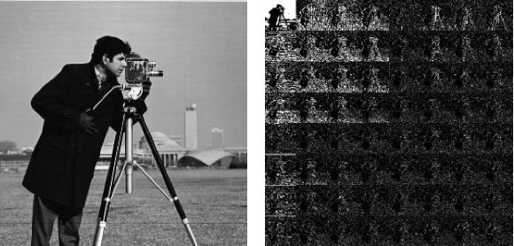
The following picture shows some of the DCT features in arranging the frequency components of the input image and its ability in edge detection.

2. Block Diagram


The block diagram

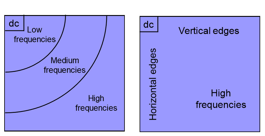
We, in our project, have implemented the computation model made by Madisetti and Willson. The input image block is chosen to be an 8*8 matrix which is replaced later by two 4*4 matrices due to the symmetry feature of the DCT. In such a way, an advantage of time complexity reduction comes from computing the DCT of two 4*4 matrices in parallel instead of one 8*8 matrix.
The matrix equation of the DCT computation model of Madisetti and Willson is given by:
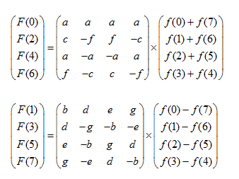
                               

Where:
acf and bdeg stand for the DCT coefficients.

The conduction of 2-D DCT (for a 2-D image input) will be based on computing 1-D DCT from the equation above two times in a row, one time for the rows of the input block and another time for its columns. So that, the number of logical elements consumed by the FPGA chip and time complexity will be reduced maximally.
The core of the computation process is to multiply the DCT coefficients matrix with an ordered input of image pixels.
The following figure shows the block diagram of computing 2-D DCT based on 1-D DCT
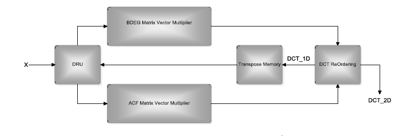
Figure -3-

  • DRU stands for Data Re-order Unit which takes care of arranging the input sums and differences in the desired way as put in the matrix equation before doing multiplications.
  • BDEG and ACF units refer to the DCT coefficients arranged in two 4*4 matrices that need to be multiplied, both in parallel, with the ordered input and these two units are made of multipliers and accumulators.
  • DCT Re-Ordering is the unit responsible of dealing with the outputs of both BDEG and ACF at the same time. Since their outputs aren’t ordered sequentially DCT Re-Ordering unit arranges them like F(0), F(1), F(2), …, F(7). It’s important to note that there are two types of outputs;             1-D DCT samples that come out after applying ordering and multiplication procedures on the rows and 2-D DCT samples that come out after repeating the same process on the columns.
  • Transpose Memory is a 2-D buffer that stores (or writes) 1-D DCT samples “row by row” and reads them “column by column” so that DCT can be conducted for the second time “on the columns” afterwards. Then 2-D DCT samples are ready to come out from DCT Re-Ordering unit.

The Inverse DCT can be processed similarly but with different coefficients.

As mentioned before, DCT/IDCT is important and considered as a preparatory process for compression. In our project, compression will be made mainly by quantization and de-quantization. Through which different qualities of the output image can be selected according to the target application. The output image can be displayed on a VGA monitor or a PC display screen interfacing to the FPGA kit or used for other applications

3. Intel FPGA Virtues in Your Project

  • A flexible environment made based on FPGA platform that can interface with different I/O types such as cameras and PCs.
  • A symmetrical feature comes from modeling two parts on one chip. A DCT/quantization block representing a transmit side and IDCT/De-quantization block representing a receive side.
  • A potential design for implementing more advanced standards like JPEG and MPEG and can be developed to suit video processing systems.

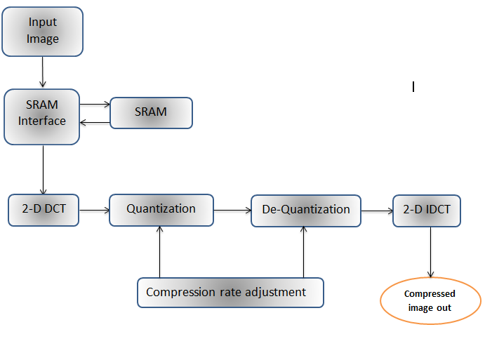
In conclusion, this design can offer many solutions in the context of signal processing and telecommunications. Its flexibility and independence built by FPGA technique has made it a competent choice in the world of embedded systems.

4. Design Introduction

5. Function Description

6. Performance Parameters

7. Design Architecture


40 Comments

Pedro Miguel Baptista Machado
The project is incomplete and it lacks for not having information.
🕒 May 28, 2018 11:44 AM
Marwa
Good luck
🕒 Jan 28, 2018 04:20 PM
Marwa
Good luck
🕒 Jan 28, 2018 04:20 PM
jalal
الله حيووووو
🕒 Jan 28, 2018 12:37 PM
Khalid Gussin
Hope the best...
🕒 Jan 28, 2018 08:15 AM
Ameer Naji
Good luck Bilal, you deserve the best...
🕒 Jan 27, 2018 02:04 PM
Majd zghieb
Proud of u ❤
🕒 Jan 26, 2018 06:14 PM
Donald Bailey
Are you also planning to implement the Huffman / arithmetic coding required for JPEG compression?
🕒 Jan 25, 2018 09:10 PM
EM103🗸
As you can see sir, We have completed the hot part of the project.. we have plans to develop the applications of this project to make it more useful and flexible to the end user. Besides, additional development on the compression algorithm is in our future plans for the next stage.. since you are speaking about Huffman coding, we'll put it on the top of our search list..
🕒 Jan 26, 2018 08:47 PM
abdullah
Good luck
🕒 Jan 23, 2018 03:50 PM
Hiba Abdulmonem
Good luck.. You deserve it
🕒 Jan 23, 2018 03:46 PM
abd alrahman
Good job guys ..wish u all the best
🕒 Jan 23, 2018 11:13 AM
asmaa
great work all the best
🕒 Jan 22, 2018 07:21 PM
Bing Xia
Good idea, keep going.
🕒 Jan 19, 2018 07:04 AM
EM103🗸
Thank you for letting us share our project.. we hope that our project will fulfill the aims of this competition.. Best regards.
🕒 Jan 22, 2018 07:49 AM
Mohammad solyman dawod
Good luck
God reward you
🕒 Jan 18, 2018 06:59 PM
mohammad dawod
كل توفيق ان شاء الله يا علوش
🕒 Jan 18, 2018 06:51 PM
berkay egerci
keep going! good project and good luck !
🕒 Jan 14, 2018 09:18 PM
berkay egerci
keep going! good project and good luck !
🕒 Jan 13, 2018 10:01 AM
wesam nage
Good luck..awesome idea and project
🕒 Jan 12, 2018 03:32 PM
kemal eddin ahmedzad
like it
🕒 Jan 12, 2018 01:21 PM
EM103 🗸
Thanks for your comments
🕒 Jan 12, 2018 12:00 PM
MOHAMED
Good Project. Keep moving.
🕒 Jan 12, 2018 02:23 AM
Raafat Cattan
I think that will be good for decrease size and better for transport in network with low cost traffic.
best
🕒 Jan 11, 2018 09:50 PM
EM103🗸
That's exactly the aim of the project.
Thanks for your comment
🕒 Jan 12, 2018 11:59 AM
Hassan anzarouti
Good presentation, wish you the best
🕒 Jan 11, 2018 11:30 AM
Munzer Rashed
great work.. I wish you the best
🕒 Jan 11, 2018 10:12 AM
samer kosaibati
very nice project ,Good luck
🕒 Jan 11, 2018 09:49 AM
Kusai
Interesting project guys.....good luck
🕒 Jan 11, 2018 07:56 AM
abdurrahman
iyi şanslar
🕒 Jan 11, 2018 05:01 AM
Moris
Despite war and all the challenges you made it
Well done champions
🕒 Jan 10, 2018 11:24 PM
Emad Alsagheer
God bless and good luck :)
🕒 Jan 10, 2018 01:26 PM
Nour alien Mattini
Hard luck Bro
🕒 Jan 10, 2018 10:08 AM
Raad kasem
Interesting.... Hope you win
🕒 Jan 10, 2018 09:40 AM
Abdullah Rasho
Wonderful idea which deserves attention and vote. Hope you win
🕒 Jan 10, 2018 06:30 AM
Mohammed Ebesh
Good luck
🕒 Jan 10, 2018 03:29 AM
wassem Abd Alrazaq
very good ...
🕒 Jan 10, 2018 01:05 AM
Wissam Al-Sheikh
I hope you guys the best.
🕒 Jan 10, 2018 12:01 AM
Mohammed
Good luck
🕒 Jan 09, 2018 11:40 PM
Ahmad
Good luck.. interesting topic!
🕒 Jan 09, 2018 10:27 PM