PR015 » 基于FPGA的环视辅助驾驶图像系统
智能驾驶时代即将来临!随着汽车的大范围普及,辅助驾驶系统的需求越来越大。我们计划利用FPGA快速并行的运算能力,开发一套实时的环视显示辅助驾驶图像处理系统,使得驾驶更加安全舒适。我们将在采用四路鱼眼摄像头作为视频输入,在DE10-NANO平台上经过软硬件算法协同处理,输出俯瞰视角的车辆环视影像。这一套系统将能大大降低驾驶事故发生的概率,大幅降低泊车难度。
The era of smart driving is coming! With the widespread use of automobiles, there is an increasing demand for assisted driving systems. We plan to use FPGA's fast parallel computing capabilities to develop a real-time look-around display assisted driving image processing system that will make driving safer and more comfortable. We will use a four-way fish-eye camera as a video input, and the DE10-NANO platform will be collaboratively processed with hardware and software algorithms to output a bird's-eye view of the vehicle. This system will greatly reduce the probability of driving accidents and significantly reduce the difficulty of parking.
demand analysis
With the rapid development of image and computer vision technologies, more and more technologies are being applied to the automotive electronics field. Traditional image-based reversing imaging systems only install cameras at the rear of the vehicle and can only cover a limited area around the rear of the vehicle. Blind areas around the vehicle and at the front of the vehicle undoubtedly increase the potential for safe driving. Collisions and scrapings are prone to occur in narrow and congested urban areas and parking lots. In order to enlarge the vision of the driver, it must be able to perceive a 360-degree environment, which requires the coordination of multiple vision sensors and then through video synthesis to form a complete set of video images around the entire vehicle. Demand, look around assisted driving image system came into being.
working principle
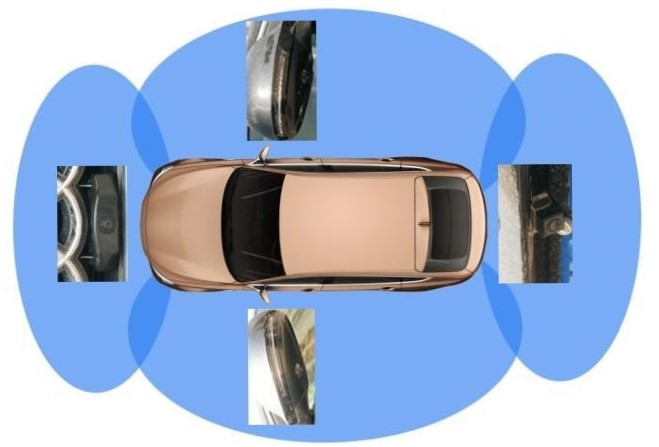
Looking around the assisted driving image system, it mainly includes: four fisheye cameras installed around the car, DE10-NANO platform as a data processing platform, on-board monitor; the camera photographs the car front and rear left and right images respectively, and the images are captured by four fish-eye cameras After collection, it is transmitted to the DE10-NANO platform, after a series of fish-eye distortion correction, perspective projection transformation, image bilinear interpolation, four-channel image coordination, four-channel image mosaic processing, synthesis of a road top view, transmitted by HMDI On-board monitor displays panoramic image information of the car and its surroundings.
Function and effect
Looking around the system set up around the car to cover all the field of view of the vehicle around the four fisheye camera, collected at the same time the multi-channel video image processing into a 360 degree view of the vehicle around the body, and finally in the car console screen The above shows that the driver can clearly see the presence of obstacles around the vehicle and understand the relative position and distance of the obstacles, helping the driver to easily park the vehicle. Not only is it very intuitive, but it does not have any blind spots. It can improve the driver's ability to calmly control the parking of vehicles or pass through complex roads, effectively reducing the occurrence of accidents such as scratching, collisions, and trapping. It provides more intuitive assisted driving image information for car driving, and has a very good application prospect in car assisted driving and car safety.
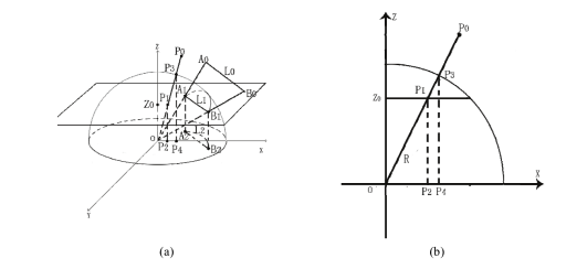
Figure 1 The principle of fisheye correction
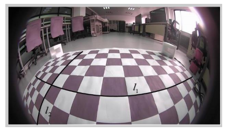
Figure 2 Pre-correction image
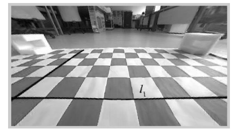
Figure 3 Corrected image
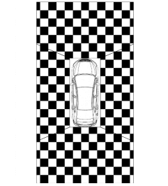
Figure 4 Splicing principle
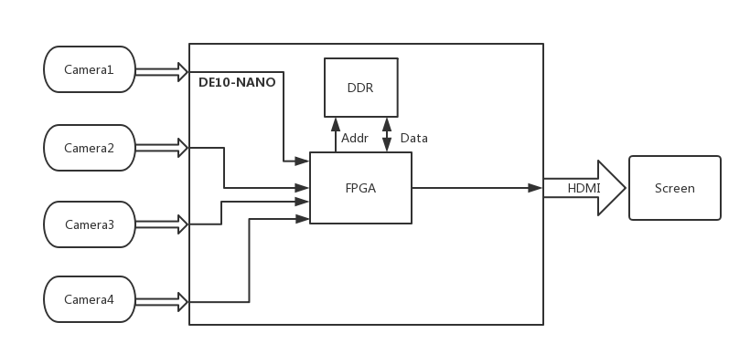
Figure 1 system block diagram
Parallel processing
Thanks to the FPGA parallel work, we can simultaneously process four input video signal, greatly simplifying the difficulty and complexity of the system design.
Real-time processing
The on-board assisted driving system has high requirements on real-time performance, and FPGA has a great advantage compared with CPU in real-time. We can complete processing and stitching of four images with extremely low latency.
A lot of calculations
Due to the large number of operations and processing of images on the viewing system, there is a high requirement for the hardware's computing power. FPGA has a powerful computing capability and can greatly increase the speed of calculation.
According to statistics from the Traffic Management Bureau of the Ministry of Public Security, as of the end of 2016, the country’s vehicle ownership was 194 million, and the new registrations and annual increments reached the highest levels in history. With the continuous improvement of people's living standards, the rigid demand for automobiles remains strong, and the number of car ownership maintains a rapid growth trend. However, due to structural constraints, there is a blind spot of about 60° around the car, and the external information obtained by the driver is mainly visual information, which brings certain safety risks to safe driving. There are more than 310 million motorists. In addition, for young drivers with relatively short driving experience, in the wrong car, parking, and through narrow roads and bridges, blind spots in the field of vision will bring a lot of trouble. According to statistics, there are no fewer than 500,000 traffic accidents caused by the blind spots in the world every year.
As the visual basis of human perception of the world, images are an important means for humans to obtain information, express information, and transmit information. They are also technologies that are gradually emerging and can help people understand the world more objectively and accurately. Therefore, the look-around display based on image processing will bring great convenience to people.
Looking around the display as a component of advanced driving assistance will help improve the safety and comfort of the car. The look-ahead display technology, anti-lock braking system (ABS), and reversing image technology are equivalent to automotive active safety technology, which is the safety design adopted to prevent car accidents and improve driving safety. However, the appearance of the look-ahead display technology was relatively late. Kato K, Suzuki M, and others first proposed the concept of look-around display in 2002.
The current look-around display technology research results use fish-eye cameras and omnidirectional cameras. Ehlgen T, Pajdla T et al. implemented a truck look-around display system in 2007 using a 360° field of view omnidirectional camera. Liu YC, Lin KY, et al. proposed a look-around display system in 2008 that uses fisheye cameras with a field angle of 140° and 170°. The system can have a large collection range. In 2007, Nissan used the Surround View Monitor (AVM), a 180°FOV fish-eye camera, to cover a “hemisphere” output range such as road surfaces. Currently most of the look-ahead display technologies use 180-degree angle-of-view fisheye cameras for image acquisition. In addition, the existing look-around display technology research results also include 4-way, 5-way, and 6-way programs.
At the same time, the research results of current look-ahead display technologies include different kinds of processing platforms, such as DSP, FPGA, ARM+DSP, ARM+FPGA, and so on. In 2013, Chang YL, Hsu LY and others used ARM+DSP architecture to propose a self-calibrated look-around display system based on TI DaVinci DSP platform. Zhang B, Appia V et al. proposed an embedded system look-around camera solution based on the DSP C66x platform in 2014. In 2015, Renesas Electronics introduced the R-Car H2 SoC-based look-around display system kit. The ARM, DSP platform has the algorithm to achieve the benefits of flexibility, and FPGAs have advantages in processing speed due to their powerful data parallel computing capabilities.
Look-around display technology has shown a gradual increase in resolution. Ehlgen T, Pajdla T et al.'s 2007 truck look-around display system has an input resolution of 480p. In 2013, the self-aligned look-around platform proposed by Chang YL, Hsu LY et al., and the input resolution were also 480p. In 2014, Zhang B, Appia V et al. proposed an embedded system look-around camera solution with a resolution of 720p. At present, mainstream mature products mostly adopt 1280×800 resolution. For example, Renesas Electronics introduced the RCar H2 SoC-based look-around display system kit in 2015 and the 360° 3D panoramic system Omniview developed by Fujitsu in 2016.
In the output display effect, also made great progress. In 2014, Rottner G and Sejalon FM et al. proposed a brightness-balanced look-around display technology capable of coordinating the brightness of each stitched image, and obtained a better display effect. Desai Xiwei has introduced a 3D panoramic car vision viewing system capable of realizing 3D viewing angles. In terms of video splicing, there are mainly two methods of seam splicing and seamless splicing. Mainstream products currently use video output that is seamlessly spliced. Domestic car manufacturers have also achieved certain research results and developed a series of products. Domestic auto brands such as BYD and Geely have all launched 360-degree look-around display systems with independent intellectual property rights. Domestic universities like Tsinghua University and Xi'an Jiaotong University have also achieved certain results in this direction.
At present, the look-around display is developing in the direction of 3D, multi-view, high-definition display, and seamless splicing. At the same time, the look-ahead display is being deeply integrated with other ADAS technologies (such as pedestrian warning and lane detection), which makes driving more intelligent.
Ⅰ.INTRODUCTION
This project aims at achieving real-time look-around display, adopting techniques such as image distortion correction and multi-graph joint calibration.Design algorithms such as image stitching to realize the ability to finally look around the output to achieve real-time monitoring of the surrounding area of the vehicle. The effect of the environment. The main tasks of this project are image processing algorithms, video stitching algorithm improvements and overall system Design and implementation.
The entire project is collected from the video source to the final look-around output and will use the flow chart shown in Figure 1 below.
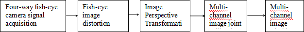
Fig.1 System flow diagram
This project uses a fish-eye camera to collect 4 images and finally output them to the monitor. The look-around display system solution can output the look-around image of a vehicle with a bird's-eye view through a four-way fish-eye camera installed around the vehicle body and through collaborative processing of hardware and software algorithms. First of all, establish the system's overall design ideas and framework, determine a series of key feature parameters around the function, and plan the software and hardware collaborative processing algorithm framework. Then, the overall system is divided into software and hardware, and the functions implemented by the hardware and software are planned in detail. Secondly, the module circuits of hardware and software systems are designed. Particular attention is paid to the module structure, design ideas and details. The process of image acquisition, image transmission, image storage, image processing and image display, and system control are combined with the Terasic DE10-Nano development board and corresponding hardware and software interfaces. The fisheye lens was selected because the fisheye lens has a wide viewing angle range and can capture external information at a viewing angle of 180 degrees. After the distortion correction and viewing angle conversion in the later stage, the two-dimensional image information that can be comfortably recognized is output. Video signal processing was performed on the Terasic DE10-Nano development board throughout the entire process. The input image is stored after a series of processing, and the image is stitched using the lookup table method. The display process of the output video signal No. 6, including the video signal written to the memory, and a certain regular video signal output method. The entire output requires the coordination of the system clock and the video interface. Including RAM read and write, single video output, etc. After the final signal processing, the output looks around the video.
The entire system contains more algorithmic designs. Fish-eye distortion correction algorithm, perspective projection transformation algorithm, four-channel image coordination algorithm, four-channel image mosaic algorithm. The process also includes some basic image processing techniques, image input processing, sampling format conversion, and color space conversion. The image is stitched and the algorithm is first designed. At present, it is planned to use a pixel coordinate mapping look up table generation algorithm to implement the stitching of images.
The implementation of this paper is mainly based on the Terasic DE10-Nano development board, supplemented with other necessary hardware. A fish-eye camera with four 185-degree viewing angles was used to collect signals from the outside world. Through the collaborative work of hardware and software, output real-time monitoring. During the project verification process, a creative combination model is used to design and build a system simulation and test car platform, and it is possible to easily and accurately adjust the installation angle, height, and position of the image sensor, and at the same time, be able to move quickly, and have fast access to system parameters. Significance.
Ⅱ.ALGORITHMS & IMPLEMENTATIONS
This chapter includes the main parts of the overall system implementation process, including fish-eye correction, image Perspective Transformation, and image splicing.
In order to obtain no dead angle information around the vehicle, this design uses 4 fisheye lenses as the input signal. The fish-eye lens has a severe barrel distortion with respect to the normal lens, so the input image needs to be corrected.
Due to the large field of view of the fish-eye lens, we must use a spherical perspective projection model to represent these images.Like, but what we see in everyday life is an image under a planar perspective projection model, so we want to use these image, it needs to be converted into a familiar perspective projection image, that is, using a flat perspective projection model table Illustrated image. The fish-eye lens imaging model is shown in Figure 2. The connection between any point P0 in the space and the projection center O is shown in Figure 2.The intersection of P3 and P3 is projected to point P4 on the imaging plane to form the image point of the P0 point in the fish-eye image, and the space is straight.The line L0 is projected onto the projection plane to form a large circle of the projection surface and then is projected to the imaging surface to form a circle in the fish-eye image.

Fig.2 Spherical perspective projection correction model
Correcting a fish-eye image requires converting the fish-eye image into a familiar planar perspective projection image. As shown in Fig. 2, the plane Z0 is parallel to the plane XOY, and the connecting line between P0 and O crosses plane Z0 at point P1. The simplified diagram is shown in Fig. 2. If the coordinates of P1 point are (x1,y1,z), P4 coordinates are (u1,v1,0), Z0 point coordinates (x0,y0,z), O point coordinates (u0,v0,0) can get formula (Eq.1), where R is the radius of the ball.
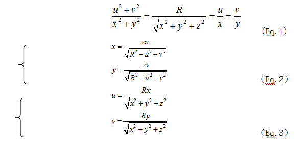
According to the formula (Eq.3) in the fish-eye correction algorithm, the entire parameter calculation process is a pipelined calculation. This type of calculation is easily implemented in the FPGA. The following figure shows the hardware implementation process.
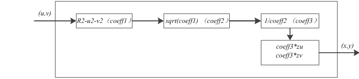
Fig.3 Fish-eye hemisphere correction hardware implementation
When the image is captured, the camera is not perpendicular to the ground. Therefore, Perspective Transformation is required for the image.
Perspective Transformation is a transformation that projects an image from the plane where the image is located onto another new View Plane. If the ground is regarded as a new View Plane, according to the principle of camera imaging, the image we collect is actually the projection of the object on the ground plane in the imaging plane of the camera. On the other hand, the actual object on the ground is the projection of the image on the imaging plane in the ground plane, as shown in Figure 4.
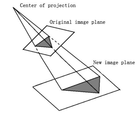
Fig.4 A schematic perspective view of the projection
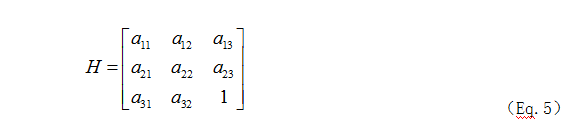
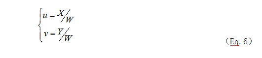
If the point coordinates on the imaging plane of the camera are represented as homogeneous coordinates[X Y 1]T and the coordinates of the corresponding points on the ground vision plane are represented as homogeneous coordinates[X Y W]T, Then according to the principle of homography mapping, there is the following relationship between these two coordinates.
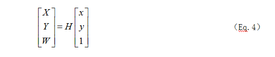
Where H is a 3*3 homography matrix, homography is a concept in geometry, and homography is an invertible transformation from the real projective plane to the projective plane. The homography matrix can be used. Mapping a point on one view plane to another new view plane, while having a feature that a straight line is still mapped as a straight line under this transformation.
The Perspective Transformation hardware implementation shown in Figure 5
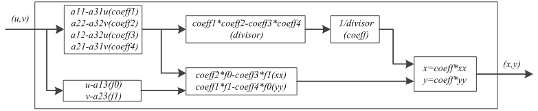
Fig.5 Perspective Transformation hardware implementation
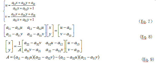
In order to prevent the appearance of holes in the image transformation process, it is necessary to use inverse operations of the transformation process.
It can be known from the principle of homography that the coordinates of the corresponding point in the new image after the transformation are (u,v).
The reasoning process of inverse transformation of homography mapping is as follows:
The main function of image splicing is to process the four-path overhead image of fisheye correction and projection transformation as the final output image. Because four fisheye lenses are selected for shooting in this design, there is a certain overlapping area in the four-way overhead image, and the edge of the image after fisheye correction cannot be completely corrected. Therefore, effective areas must be selected during the stitching process. The splicing process is a top view of the surrounding vehicle body.
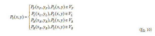
All four images are the overlapping areas of the image in the lower left and right areas of the image. The commonly used method is feature matching. Feature matching mainly utilizes detecting the feature points of an object in an overlapped portion and overlaying the feature points together, thereby connecting the two images together. However, because the edges of the image cannot be completely corrected, the effect of using the overlapped portion to perform the stitching is not very good. In this design, a plane rectangular coordinate system is established on the ground. The images of the four fields of view share the same coordinate system. In this way, the top view coordinates of the sample points selected in the top-view conversion process belong to the same coordinate system. Therefore, after the conversion into the top view image, the relative position of the actual image does not change. A mapping may be established based on the coordinate relationship between the coordinates of each top-view image and the finally output image. The stitching algorithm is shown in formula (eq.10).
After image stitching, the resulting image of the look-around display is shown in Fig 6 .
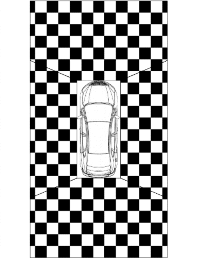
Fig.6 Splicing algorithm schematic
After designing a complete system, we verified each algorithm module separately.
In fish-eye correction, the input is an image of a fish-eye lens, which eliminates its barrel distortion during the correction process. In this design, in order to facilitate the initial test verification, the fish-eye diagram is used to test the feasibility of the algorithm and then the color bar signal is used for testing. This is because the actual lens output can be configured in the color-bar mode, which greatly improves the efficiency of the test.
In the algorithm verification, the input image is a fish-eye lens image, and the optical axis of the fish-eye lens and the target object are not perpendicular, which is in accordance with the actual situation.
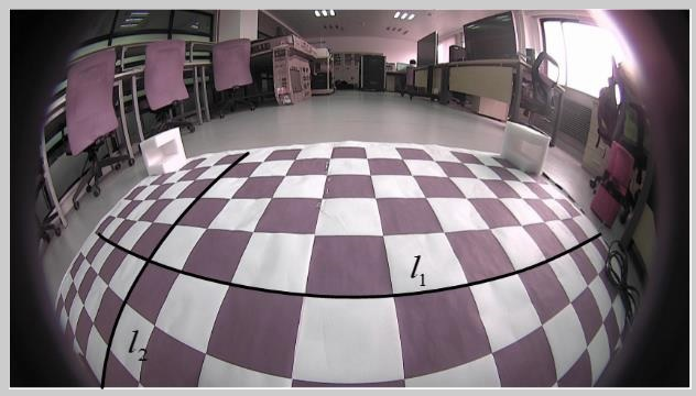
Fig.7 Algorithm verification input fish-eye diagram
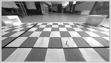
Fig.8 Algorithm verification output fish-eye diagram
From the comparison of the above two images, a fish-eye correction algorithm can be found that can straighten the curved straight line.The corrective effect is good and can meet the needs of the experiment. From the corrected figure, it can be seen that the white and black information on both sides is lost. This is because the information on both sides of the reality is redundant. In this process, the corrected output image is filled from the nearest hole using the nearest neighbor interpolation.
The following two pictures are the picture input by the correction algorithm and the picture output after correction.
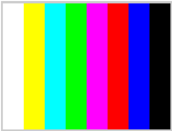
Fig.9 Input color-bar diagram
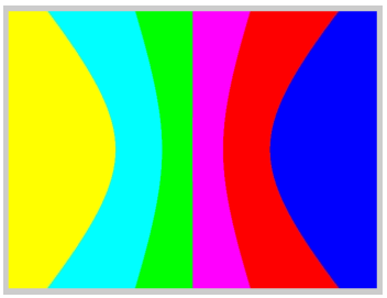
Fig.10 Output color-bar diagram
After the algorithm is verified, enter the colorbar image to facilitate subsequent modelsim and FPGA verification.From the corrected figure, it can be seen that the white and black information on both sides is lost. This is because the information on both sides of the reality is redundant. In this process, the corrected output image is filled from the nearest hole using the nearest neighbor interpolation.
In Modelsim verification, 100% color bar is used for testing. The blue part on the right and the blue part on the bottom of the figure are the blanking parts of the image.
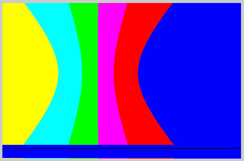
Fig.11 Modelsim verification diagram
The following figure shows the output of the corrected image after the fish-eye lens is configured as color-bar.
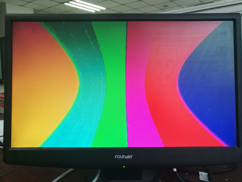
Fig.12 FPGA verification diagram
To verify the image perspective algorithm, enter a photo with a non-vertical viewing angle to verify the perspective projection algorithm.
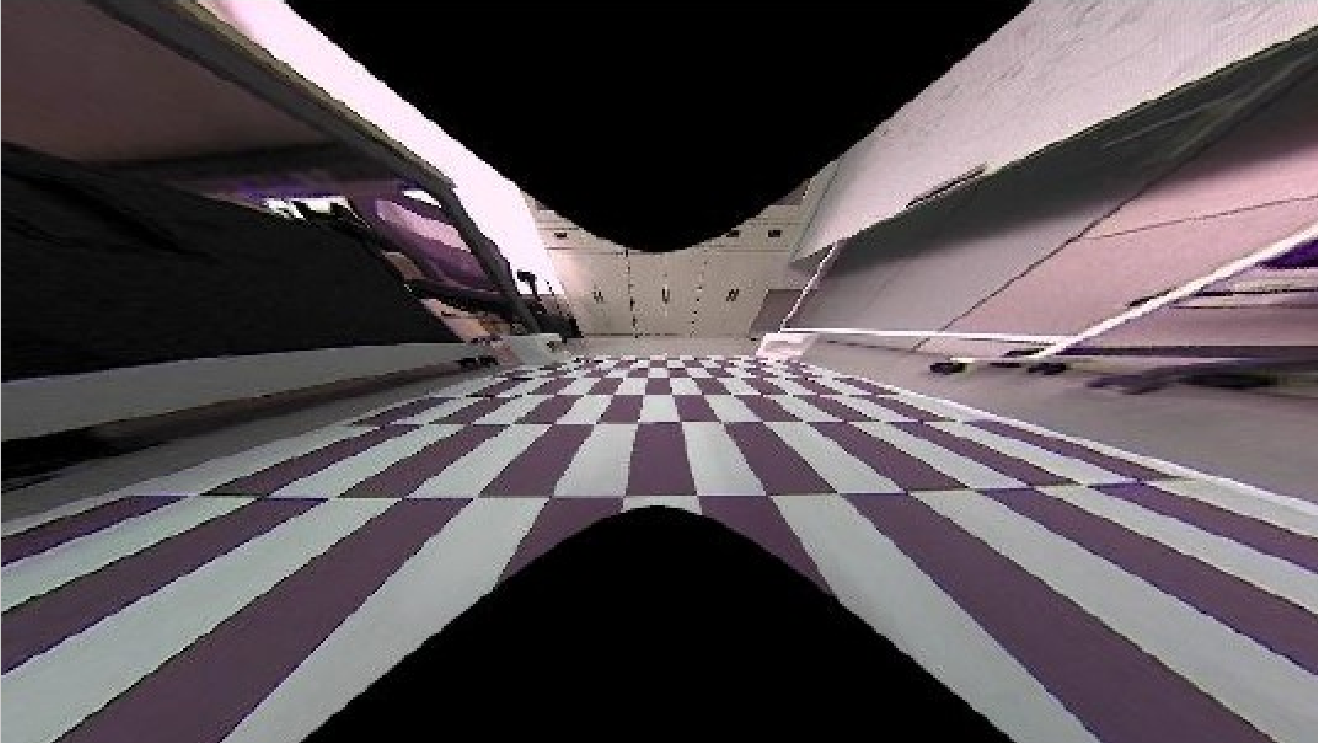
Fig.13 Perspective Transformation input diagram
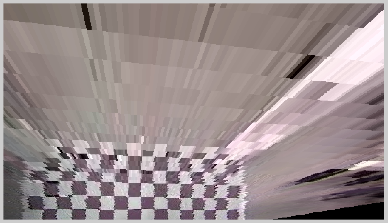
Fig.14 Perspective Transformation output diagram
By comparing Figure 13 with Figure 14, we find that the algorithm can well transform the perspective of the image.
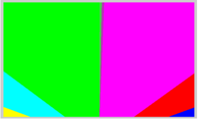
Fig.15 Perspective projection algorithm output image
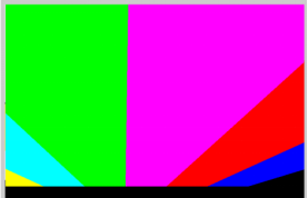
Fig.16 Perspective projection algorithm modelsim output image
The lower edge black in the figure is caused by the blanking period. In addition, it is consistent with the matlab simulation.
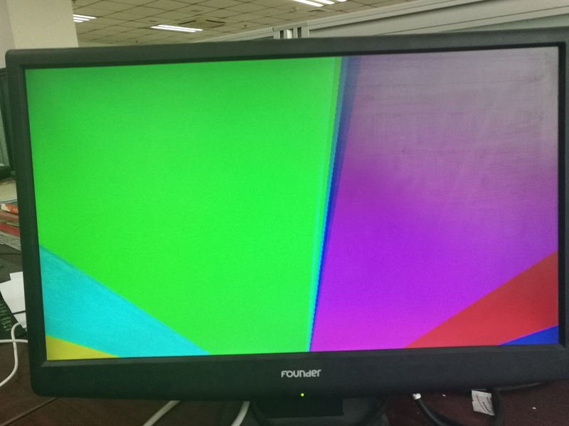
Fig.17 Perspective projection algorithm FPGA output image
It can be seen that the simulation results are consistent.
In matlab verification, use 100% color bar to test and verify whether it can be stitched. Assume that the top view image of each way is color bar. The resulting test results are shown in Figure 22.
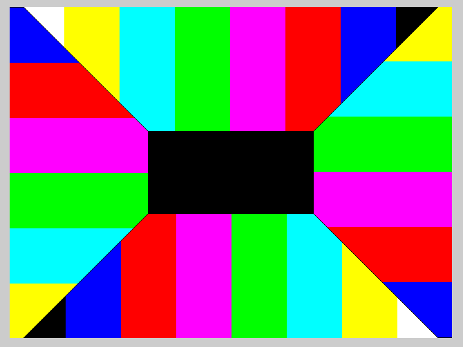
Fig.18 Image stitching algorithm verification
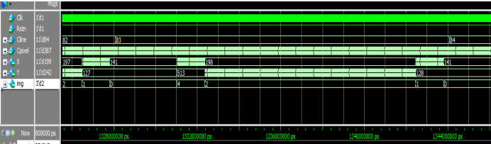
Fig.19 Image stitching algorithm verification
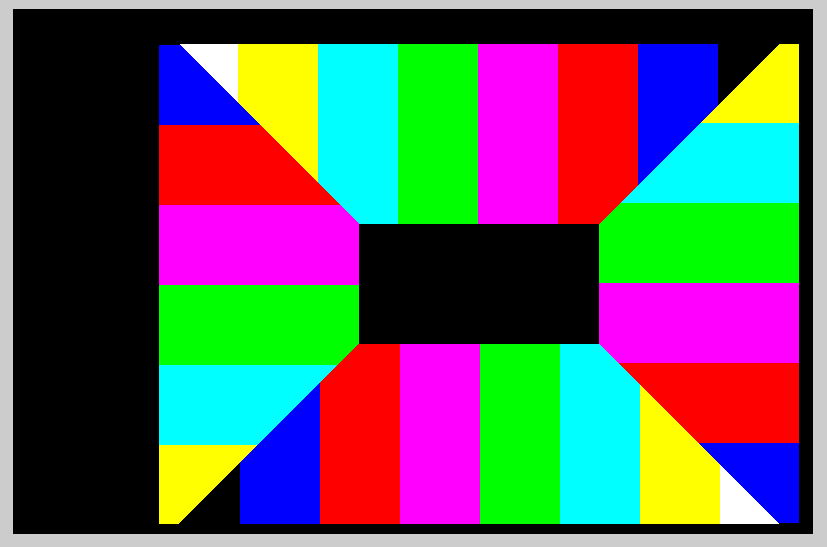
Fig.20 Image splicing Modelsim verification output image
The black area in the figure is the blanking area in the video signal and will not be displayed in actual applications. The shape of the color bar area is the same as that seen by maltab, and the resolution is 640*480.
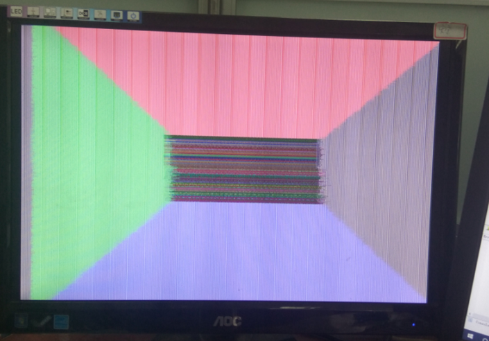
Fig.21 Image stitching FPGA verification output image
The verification process uses four-way solid color images for verification. In Figure 21, the color in the middle is indefinite because the output of this section is random during the verification process. From Figure 21, we can see that the image mosaic algorithm meets the design requirements.
Ⅲ. CONCLUSION
The look-around display system proposed by this design has broad application prospects. For a manned car, the 360° ring car top view it provides can be applied to various driving scenarios such as parking, wrong car, reversing, narrow space passage, etc. to prevent vehicles from scratching and paralyzing and to ensure safe driving. For unmanned vehicles, the surrounding image information provided by the vehicle can provide a visual data source for the functions of the unmanned vehicle to realize road surface obstacle detection, lane line detection, and the like. The look-around display system proposed by this design can continue to develop new functions for implantation, and has a considerable degree of in-depth development value. For a manned car, it is possible to add features such as lane detection, pedestrian detection, blind spot detection, etc. to make it a complete driver assistance system product. For driverless cars, vehicles can be built using perspective algorithms.The surrounding "bowl" looks around the image, thus providing a visual data source for pedestrian detection, overtaking algorithms, and other functions for unmanned vehicles.The hardware circuit and hardware algorithm video path constructed in this paper can be used to transplant other single-channel or multi-channel image processing algorithms, which has strong universality.
camera frame rate : 60fps
HDMI frame rate : 60fps
