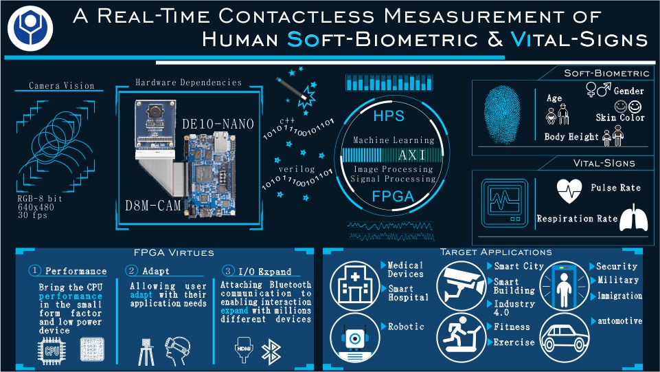
PR051 » BioVision
Vision is a gift. However, there are some things human eyes cannot see directly. Therefore machine vision technology developed to help human life. Along with this project we propose solution for multi-purpose application using machine vision technology. We are developing a contactless real-time system to measure human soft-biometric and vital signs using DE10-Nano and D8M camera as main hardware. Moreover, we are providing interfaces and peripheral which able to fulfill target application needs. We believe our system has promising benefits for human life with offers high specification and low-cost technology.
Background: with the advancement of science and technology, a system are demanded to intelligently delivers solution for some problems. Especially for critical application e.g. biomedical and security, an acurate and credible device is a must. Typically, applications related to human biometric and vital signs assessment are using several instruments to measure for each parameter. Moreover, conventional device usually are contact-based system which inconvenience in some cases (e.g. skin iritation, allergies). Therefore computer vision technology developed to build contactless system and compete with conventional method.
Purpose: we are planning about low-cost, low-power, intelligent system, and having capability for mass production in the future. Indeed, we want to realize a system not only for research purpose but also beneficial to human being. Our main purpose in this project is to extract human body information both biometric and vital signs based on contactless system using camera as the single main sensor.
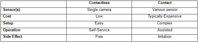
Advantages: as time goes by, contactless-based measurement of human biometric and vital sign using camera offers more and more benefits, Table 1 show the advantages contactless method compared to contact based.
Table 1 Contactless vs Contact based System
Method Review: to satisfy our purpose requirement, we end with conclusion that DE10-Nano and D8M camera are the answer. The DE10-Nano device is armed with FPGA and HPS which able to gives us more freedom to develop our system. We utilize the FPGA side to deal with raw data of vital signs, Bluetooth communication part and display, while the HPS side will take soft-biometric and vital signs measurement. Our vital signs measurement is based on remote imaging photopletysmography (rIPPG) which means extract pulse signal from change in skin color due to blood volume change in vessel. Hence, we employ the FPGA with image processing and signal processing functionality. D8M camera was used as a sensor and was controlled by the FPGA to captured images in 30 fps. In the other hand, we use machine learning algorithm to deal with soft-biometric part. Once after FPGA send a frame contain subject face, the machine learning model will extract information including gender, age, skin color, and body height. The machine learning model was trained offline inside DE-10 board, and then we export it into DE10-Nano. In the same time with measurement we provide display interface via HDMI port to visual captured image. Moreover, we send all measurement parameter to Bluetooth component that allow to interact with other device (we use smartphone in this project). All this system runs in real-time with offer high accuracy and precision.
Target Applications and User: as mentioned earlier, system we design is a solution for multi-purpose application. Shown in our image poster above, our designed system has 6 mainly target application including: medical instrumentation, robotic, smart assisting technology, exercise, security and automotive. By enabling the FPGA virtues the applications are not only limited to mentioned earlier, our project huge potential to develop more in the future.
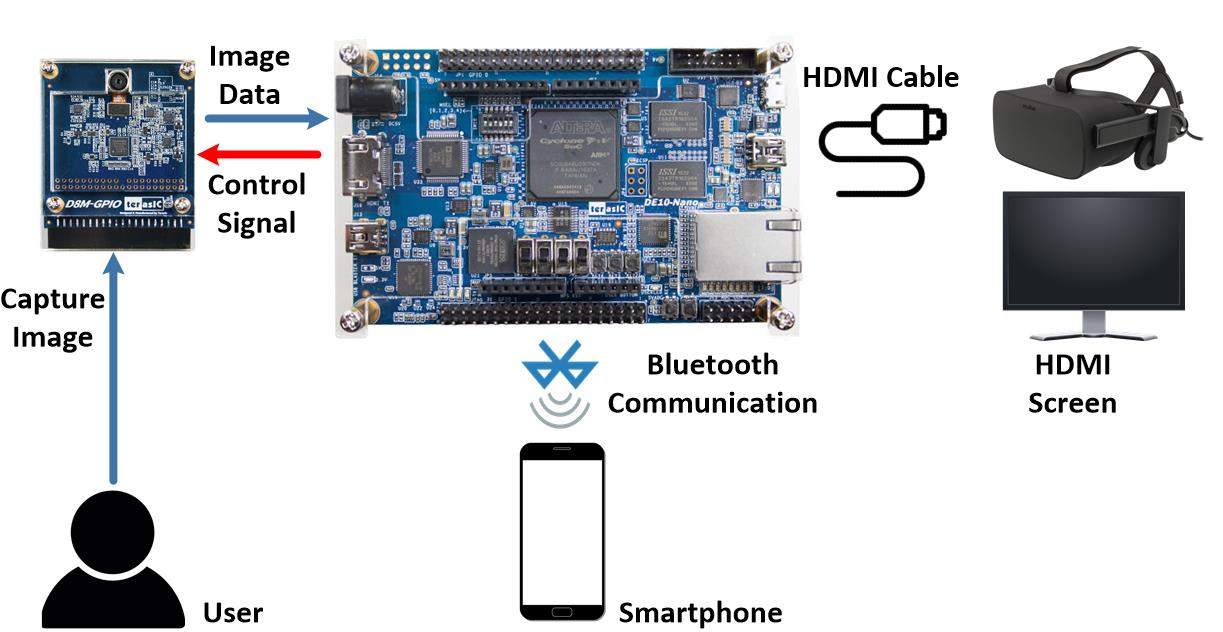
Figure 1 System Block Diagram
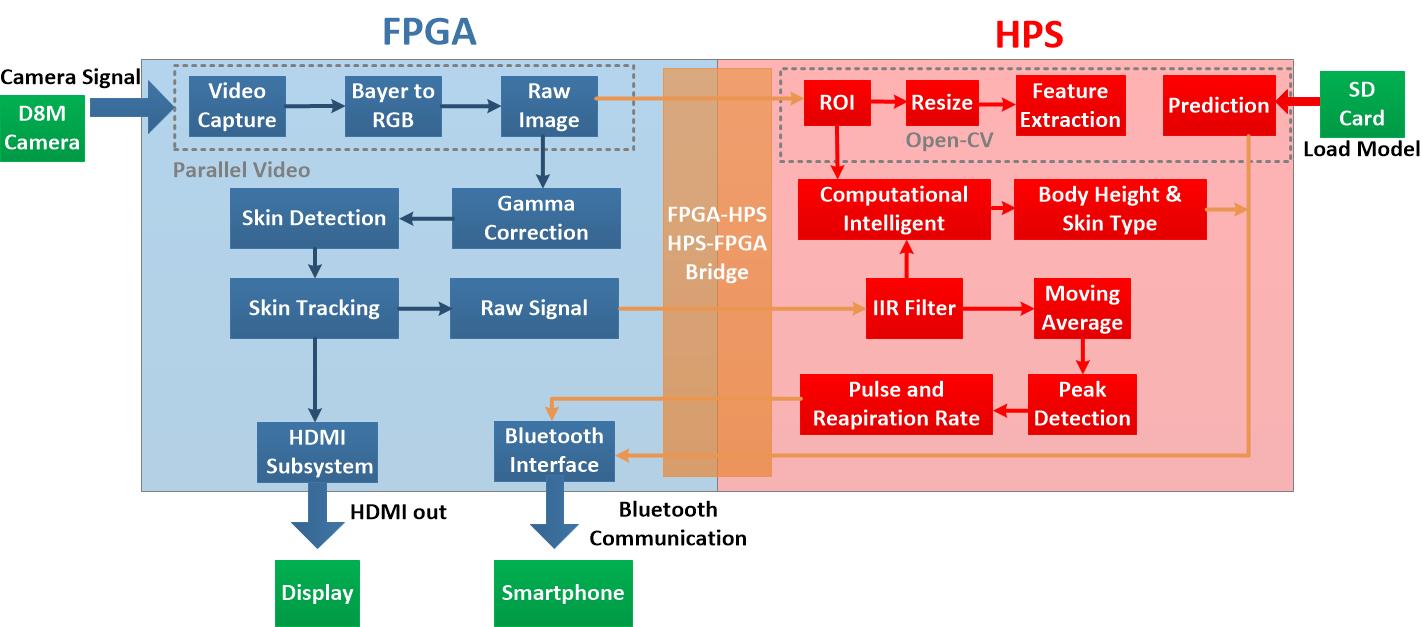
Figure 2 Front-Ent Block Diagram
Performance: Usually image acquisition performance in general CPU achieved unstable fps, therefore inaccurate measurement especially in vital signs parameter occur. The acceleration performance brought by FPGA is ideal for our proposed framework to improve accuracy and enable longterm measurement. Compared to any other processing unit with the same price point FPGA offers better performance. Performing vital signs and soft biometric measurement in FPGA are more stable compared to general CPU. We were proved by powering up our DE10-Nano board for a full week and the result our board keep performing same as initial and the SoC temperature did not change (50oC).
Some Papers related to FPGA performance are well documented here:
Adapt: FPGA is a freedom. We can liberally change, extend, or even remove the functional subsystem to adapt with application needs. As instance example, our system adapt to different light condition of the room. FPGA will obtain the information about illumination exposed to subject, if the light over expose FPGA intelligently change the gamma value and it will be perform in reverse. Evenmore, our FPGA can capture the image and prcoceed the data in the near dark illumination condition (revealed in publication [3]). Moreover, with small form factor of the FPGA or especially DE10-Nano, we can use our system in different setup and possible to bring it everywhere.
I/O Expand: By attaching universal communication device, we enabling to interact with millions other device. In this project, we use android smartphone as an example. Measured soft biometric and vital signs parameter will be send to android device for further processing. The features we programmed in our android application are visualizing and logging for both pulse rate and respiratory rate value. As well as displaying the result.
Our idea is suitable for DE-10 board as main device which having FPGA and ARM architecture.
Figure 1 show our main system diagram, our system is based on self-service operation. Users can start the system with just facing to the camera and controlling the smartphone. Once system starts, camera will capture real-time image and then send it to DE10-Nano System-on-Chip (SOC) board. Afterwards, DE10-Nano processes the images data into designated parameters. Raw images will be displayed on screen using HDMI protocol also controlled by SOC. Finally, measurement results obtained using smartphone application sent by DE10-Nano board via Bluetooth communication.
Figure 2 show our front-end block diagram, we exploit parallelization computation from FPGA part to interfacing several external peripheral which are camera (D8M), HDMI, and Bluetooth. FPGA main jobs are processing the raw image (image processing) and communication. While, we leave HPS to calculate all vital signs parameters and measure all soft biometrics parameters. Communication between the two architectures is done via Parallel-I/O (PIO) port instantiated in Altera’s Qsys system integration tool.
The following blocks are implemented on the FPGA written with Verilog language
This block is based on D8M RTL camera controller by Terasic [4]. To control camera data flow, MIPI controller was used. And then image data buffered using one dual-port-ram controller with 640 x 480 resolution and 10 bit color depth to read/write image data.
Format image data from D8M camera represented in Bayer pattern, we need to convert the data into RGB format for further process. In this state, raw RGB image formed. Image from this block also used as an input for soft biometric measurement in HPS.
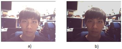
Figure 3 a) Raw image; b) After gamma correction
Once after a frame of image captured from D8M camera, as shown in Figure 3, the original contrast (a) is too bright and may cause over exposure, so we adopted a real-time gamma correction based on second order Bézier curve. The result image shown in Figure 3 (b).
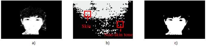
Figure 4 a) Original skin detection; b) Skin pixels distortion; c) Final skin detection
In order to segment the skin tones regions, we converted the RGB format into YCbCr model. Compared with the RGB space, YCbCr is more suitable for characterizing the skin-color because YCbCr redefines the color space in terms of 1 luminance (Y) and 2 chrominance (Cb, Cr) components. It can result in improvement of detection performance. The converting equations are shown as equation (1), (2), and (3), and converted result as seen in Figure 4 a).
|
Y = (R + 2*G +B)/4 |
(1) |
|
Cb = R-G |
(2) |
|
Cr = B-G |
(3) |
However, Figure 4 a) shows that thresholding procedure is not enough to wholly differentiate the skin tones from the backgrounds. The background objects contain with similar skin-tone color that can still be mistakenly detected. Therefore, to remove the improper skin region candidates and the background noises, a spatial filtering was performed successively as illustrated in Figure 4 b). Because the background noise usually scattered randomly through space, those pixels were considered as background noise and were removed by the following scheme. If less than 60% of its neighboring 9x9 pixels were skin pixels. The final skin detection image shown in Figure 4 c).
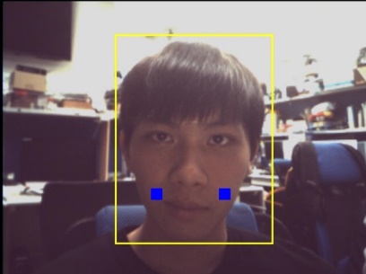
Figure 5 Skin Tracking
Afterward, we chose the cheeks area as the desired ROI in this project. Once we obtained the location of each skin tone pixel, we can estimate the cheeks position intuitively. The blue rectangle was referred as the obtained ROI shown in Figure 5. Each ROI was formed by 20 x 20 pixels.
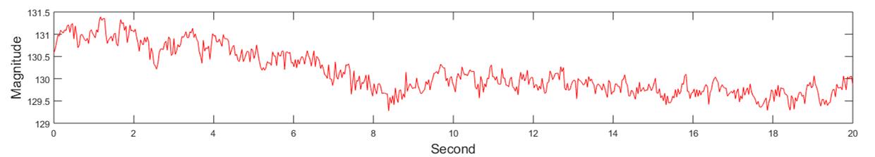
Figure 6 Raw Signal from G-Channel
The raw pulsatile signal can be obtained by computing the mean value of each RGB color channel located within the ROI (x, y) as presented in Equation 4. Example raw signal in 20 s extracted from G-channel shown in Figure 6.
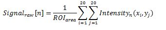 |
(4) |
As we mentioned in section before, our HPS utilization are including vital signs parameter calculation based on signal processing algorithm and also measure all soft biometric parameters based on machine learning and intelligent computational algorithm. All those parameter calculation written in C++.
Once after raw signal sent by FPGA, HPS will do real-time signal processing to measure vital signs parameter. The raw signal itself are already carry Pulse Rate (PR) and Respiratory Rate (RR) information, but it still have some noises e.g. motion artifact and illumination distortion. There are three stages signal processing before all vital sign parameters obtained, those stages describe as follows:
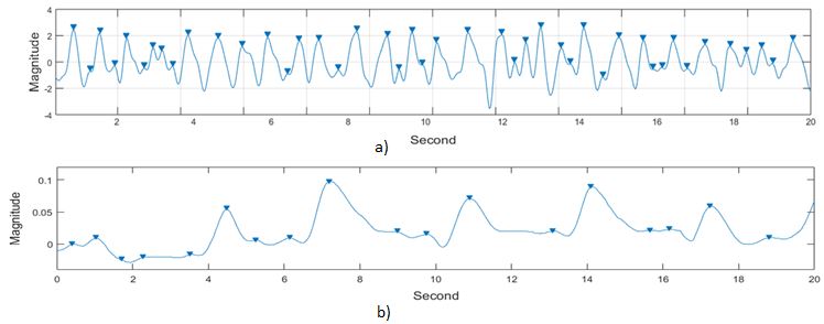
Figure 7 a) Filtered PR signal; b)Filtered RR signal
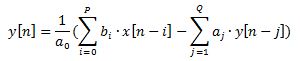
In order to separate PPG signal with noises, we adopted two digital IIR (8th order Butterworth) band pass filter. We use equation (5) as mathematic operation for filtering.
|
|
(5) |
P and Q refer to the feedforward and feedback filter order respectively which are set as 8 orders in this work. The bi and aj are the feedforward and feedback filter coefficients. x[n] is the input signal and y[n] is corresponding filter output across each frame. We were generated bi and aj coefficients using MATLAB fdatool. For PR filter, we set cut-off frequency of IIR filter around [0.8 3.4] Hz. While RR cut-off frequency filter stands around [0.05 0.5] Hz. As the results we got two different signals (PR and RR) extracted from single raw signal. Produced signal in this stage shown in Figure 7 a) for PR signal and b) for RR signal.
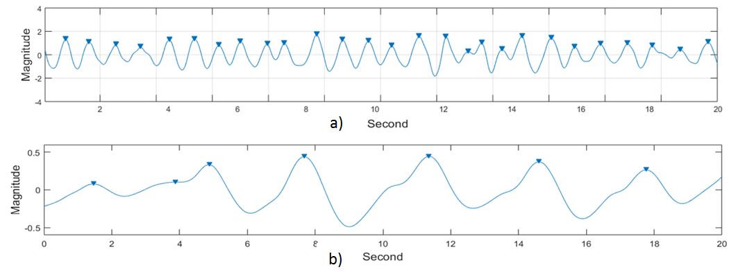
Figure 8 a) MVA PR signal; b) MVA RR signal
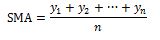
Due to non-ideal IIR filter performance, there are still some noises left on the both PR and RR signals. To avoid false positives PR and RR signal peak detection like shown in Figure 7, we simply employed Moving Average algorithm to both PR and RR signal. We use equation 6 in the real-time operation.
|
|
(6) |
Where SMA is the output signal, yn is the input signal from IIR filter, n presents as an average order, which is set as 10 here. Figure 8 shows clean PR (a) and RR (b) signal after Moving Average operation.
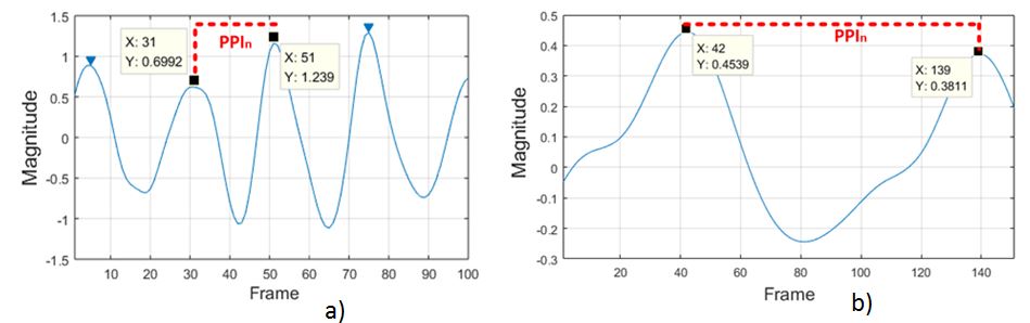
Figure 9 a) Peak detection PR signal; b) Peak detection RR signal
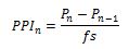
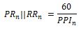
Finally, a cycle of each pulse can be estimated by detecting peaks occurrence and finding the intervals between two adjacent peaks, as illustrated in Figure 9 a) for PR and b) for RR. Thereby, the peak-to-peak interval (PPI) can be derived and transferred into equivalent both pulse rate (PRn) and respiration rate (RRn). Both parameters using equation (7) to calculate PPI and equation (8) to calculate instantaneous PR also RR.
|
|
(7) |
|
|
(8) |
where PPIn indicates as the detected peak-to-peak interval in second, which is equal to a cardiac cycle for PR and respiration cycle for RR. fs is the image capture speed of the D8M camera, which is 30 fps in this work. PRn stands for the derived instant pulse rate in beats per minute (bpm) and RRn stands for respiration rate in beats per minute (BPM).
Once after FPGA send a frame to HPS, the system will start automatically measure four soft biometrics parameters (age, gender, skin color and body height). Age and gender parameters estimation were done by employing machine learning algorithm where the model trained offline in native DE10-board. On the other hand, skin color and body height measurement are using intelligent computational technique. All parameter measurement description describe on section below.
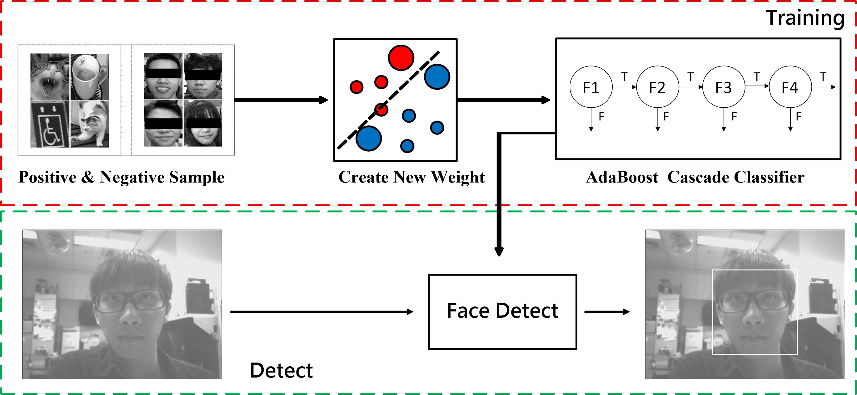
Figure 10 Face Detection
Since we only use the face region as region of interest (ROI) of an image, the first thing we need to do is to detect the face region using trained classifier. In instance, we train cascade AdaBoost classifier to deal with this job. In the training phase, we supply the classifier for both positive and negative information (images). After face detection classifier successfully built we can use it in real-time. The training phase face detection illustrated in Figure 10.
Subsequently, we need resize the ROI dimension into 92 pixels width x 112 pixels height in both training phase and prediction phase from age and gender estimation. This operation will be helpful to reduce processing time and increase prediction rate. Finally we can use resized image for age and gender estimation.
In the core of training phase in machine learning part, EigenFace feature extraction and unsupervised learning are used. EigenFace feature extraction is based on principle component analysis (PCA) method, the main purpose of PCA is to reduce the high dimensionality vector (training data) into a low dimensionality vector without losing any important message as less as possible. Finally keeping the most important and contributing dimensionality in the frame.
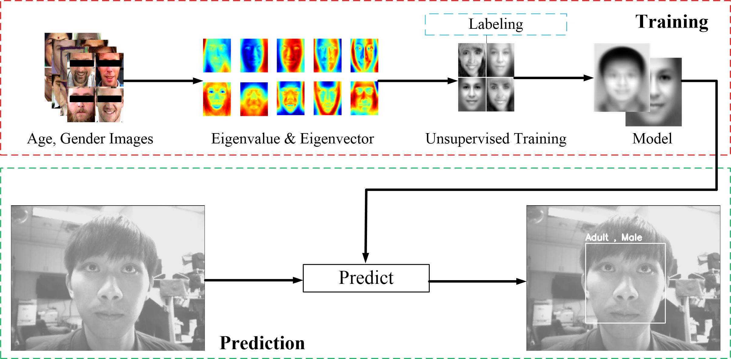
Figure 11 Age and Gender Estimation
Considering we have only small number of class prediction for both age and gender parameter. Model generation was done by applying unsupervised learning, in this work we use one-against-one Support Vector Machine based classifier.
There are 2 classes for gender estimation which are “Male” and “Female” classes, while age estimation having 4 classes including “Teen”, “Adult”, “Mature”, and “Old”. We were built our own dataset to training the model, we arrange our training dataset as follow:
Figure 11 show our age and gender estimation including training phase, also from the figure we show our example performance in prediction phase.
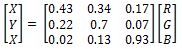
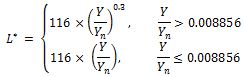
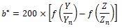
One of useful information in soft biometric measurement is skin color type. In practical, this information helps some application such as person identification. Basically, we can use several color space to obtain skin color type classification. In this work, we use individual typology angle (ITA) to algorithm to deal with this problem. ITA proved more accurate compared to others algorithm like YCbCr and RGB. We use average raw RGB signal from FPGA as input and convert it to ITA value. As beginning RGB value was acquired from FPGA, color space conversion was required. Firstly we convert RGB data into XYZ data using Equation (9), since ITA need L channel and b channel of CIE Lab, XYZ color space data will be converted into CIE Lab by applying Equation (10), (11), and (12).
|
|
(9) |
|
(10) |
|
|
(11) |
 |
(12) |
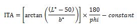
Finally, after L channel and b channel data obtained, we can calculate skin color type by calculating ITA value from Equation 13. Where constant is illumination condition, since original CIE Lab Equation is based on D65 illumination.
|
|
(13) |
The ITA based method allowed to distinguish skin type into 6 classes: very light (I) > 55o > light (II) > 41o > intermediate (III) > 28o > tan (IV) > 100 > brown (V) > -300 > dark (VI).
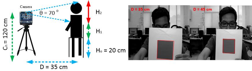
Figure 12 Age and Gender Estimation
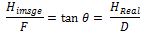
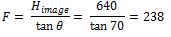
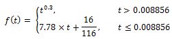
Another innovation by our work is to estimate body height using contactless method (camera). Our body height estimation is based on upper body measurement, since we have only short distance. To have best result we use static measurement setup like shown in Figure 12 a), we were setting camera height (Ch) is 120 cm and distance (D) to the subject is 30 cm. Illustrated in the same figure, body height (BH) are calculated from the sum of H0, H1, and H3. Where H0 is the height of chair, H1 is linear regression constant to estimate middle body length with function of Ch and pixel-distance value, lastly H3 is calculated by measurement using camera. So our main focus is to calculate H2. We use simple optical physics principle to deal with this phenomenon and presented in Equation 14. Where F is the focus length of D8M, and θ is the angle of view (AOV) of camera which is 70o known from D8M datasheet. Assume we have full image in 640 resolution, so we can calculate the F value and results in Equation 15. Since we had obtained F value and set D in certain value, our next step to estimate Hreal/H2 by measuring captured Himage which represent y0 position from face detection ROI. Equation 16 and 17 is used to measure H2 with known variable. As mentioned before we need to calculate H1 as linear regression of camera height and pixel-distance value. Figure 12 b) illustrated the experiment we had done to calculate pixel-distance value, we set the distance location of object (rectangle dimension 10 cm x 10 cm) and calculate the size presented in pixel. Afterwards we change the distance and calculate the pixel size again and do the regression. Finally body height (BH) can be estimated using Equation 18.
|
|
(14) |
|
(16) |
|||
|
|
(15) |
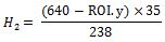 |
(17) |
|||
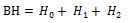 |
(18) |
|
||||
In DE10- Nano board, our external communication mainly controlled by FPGA, there are two external peripheral needs to control. The first one is for HDMI display controller and another is Bluetooth communication controller. To visualize the measurement results, we built android application which communicates with FPGA.
This block has a function to display image captured by camera in real-time operation. We utilize the controller to display 640 x 480 pixels image resolution in 60 Hz fresh rate.
We use Universal Asynchronous Receiver-Transmitter (UART) protocol to have connection with Bluetooth module. Both TX and RX of UART synthesized with 8 bit data, no parity, and 1 stop bit (8, N, 1) format. After either vital signs or soft biometrics parameter are calculated and DE10-Nanoboard connected to smartphone, data transfer can be activated. We employ our custom packet format to send the information like shown in Table 2. Where 0xFF is start packet, 0x08 is length of parameters, 0x27 is starting pointer, followed by all parameters, and “Mode” is measurement mode where “0” is vital sign measurement and “1” is soft biometric measurement, last packet 0xFE is a checksum.
Table 2 Packet Format Send to Smartphone

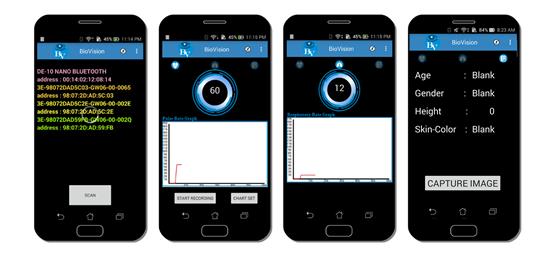
Figure 13 Android Application User Interface
We built android based application using JAVA language, to visualize all measured parameter. Furthermore, we log the HR and RR data in case the data needed for further processing. Our android user interface presented in Figure 13, the first screen will show up is Bluetooth connectivity setting. After correct device connected it will show sliding fragment to see whether vital signs measurement and soft biometric measurement results.
The following picture is our compilation report, this project used 28 percent of logic elements, and almost 13,000 registers are used, a large percentage of registers are for filtering the noise of binary image. Besides, we used 55 percent (3,000 Kbits) of embedded memory in DE10-Nano. And two PLLs for the purpose of generating audio and video reference clock. To sum up, there are still a lot of space on the board, it shows the high capability and integration level of embedded FPGA board.
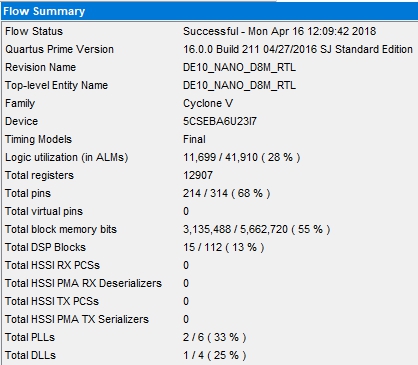
Figure 14 FPGA Utilization
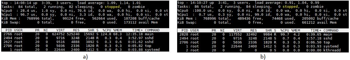
Figure 15 HPS Utilization
In order to load the age and gender model, we use around 70% of the memory on DE10-NANO.In terms of CPU, because of the ARM Cortex-A9 is kind of dual-core CPU, so when it is executing the top common, the CPU used efficiency will arrive at 200%. As Figure 15 shows, when the DE10 is performing the program about face detection, prediction and the algorithm, the CPU used efficiency will up to 125% and 105% for pulse rate detection and respiration rate detection.
We compare the performance between our DE10-Nano frameworks with FDA approved vital signs device, in this work we use GE-Dash 3000 Vital Signs Monitoring. Comparison procedure conducted in the same illumination for 5 different subjects. Our comparison results is shown in Table 3.
Table 3 Vital Signs Measurement Accuracy
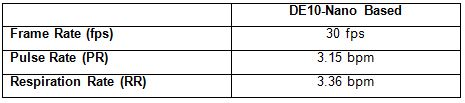
From Table 3 our DE10-Nano achieved 30 fps for sampling rate frequency which meet requirement for rIPPG algorithm. For PR and RR measurement we got Mean Absolute Error (MAE) arround 3.15 bpm and 3.36 bpm respectively compared to GE-Dash 3000. However, those value includes the agreement of quality of medical devices.
As validation we were tested our algorithm using offline dataset with amount as follows:
Prelimenary Results for DE10-Nano (without optimization)
Table 4 Soft Biometric Measurement Accuracy
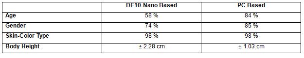
Table 4 shows the prelimenary result performance for soft biometric measurement. On this evaluation, we got unsatisfied results for age and gender detection. The main problem was insufficient memory to train the amount of data. Our PC-based has more training data compared to DE10-Nano board. The correlation between amount of data for training and the prediction results in machine learning are proved by plenty of research. However, we will keep work on it for optimization with at least achieve the accuracy goal is 90%. We are planning for another image processing algorithm done before prediction phase and also planning to use multiple feature extraction. In contrast, our skin-color type classification and body height measurement perfectly works in our DE10-Nano board.
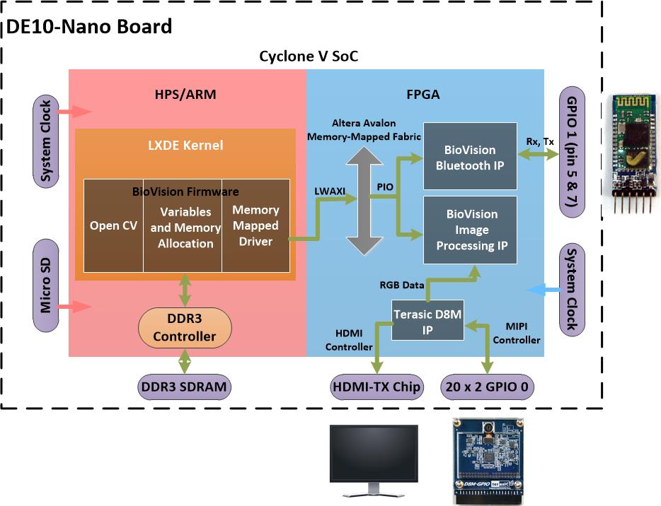
Figure 16 Hardware Architecture
Figure 16 shows our syntesized and compiled hardware architecture. There are three major IP in FPGA side, we use Terasic D8M RTL IP to deal with D8M camera and HDMI display. While the image processing and UART communication we built by ourselves to meet our requirement. Main resources in HPS are processor and the DDR3 memory, we need to allocate the memmory address used to store the variables and models. We use linux mmap() to get and send the data stream to/from FPGA.
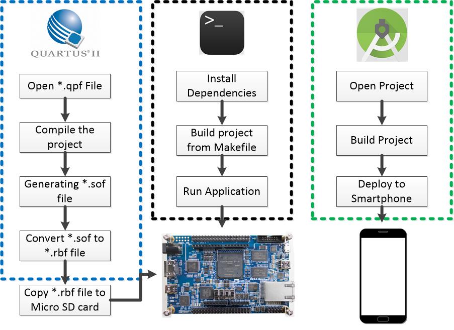
Figure 17 Software Hierarchy
Figure 17 illustrates how we embed our source code to both DE10-Nano board and smartphone. First of all, we compiling our verilog code in Quartus (we recommend to have same quartus version 16.0) and generating *.rbf file, then copy the file into SD Card memory and replace initial rbf file inside the card with our generation file. And then in linux terminal, we need to install the dependency used in our work. The most important dependency is Open CV, we recommend to use version 3.3 or higher. As the follow up, we build c++ program with the scripted makefile. Afterward we can run our compiled program. In the other side, we use Android studio to design the android application. To rebuild the project just follow the standard Android studio project building.
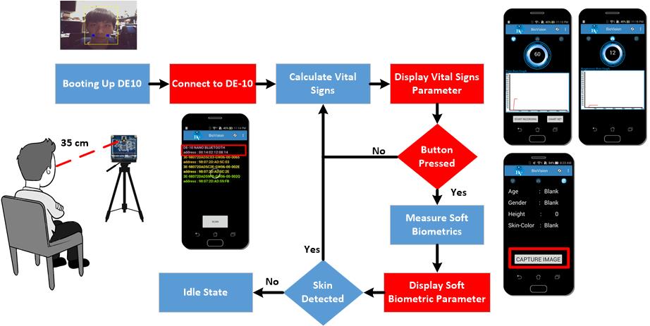
Figure 18 Framework Operation Flow
As we mentioned in the beginning, our framework operation is based on self-service operation. Figure 18 depict our framework operation, and help new user to use the system. The first thing to do is power up the DE10-Nano board, in short loading period the captured image from camera will be shown in the display device. And then the user needs to sit 35 in front of camera to get best performance. Afterwards, user needs connect the DE10-Nano with the android application. Once after two device connected, the vital signs measurement start to work as default measurement. The user can change the mode to soft biometric measurement by pressing the button in soft biometric fragment on the smartphone. All parameter calculation were showing continuously by the application. If there is no user/skin in front of the camera, system become idle until new user use the system again.
Our idea is to build a real-time contactless measurement human vital sign and soft biometric for general purpose application. Vital signs parameter were measured in this project were pulse rate (PR) and Respiration Rate (RR), while soft biometric parameter were including age and gender estimation, skin color type, and body height. In the realization, we success to build our system based on our idea. We design a framework that suitable for DE10-Nano board as a main device. We were utilized both FPGA and ARM architecture on SoC to do big part of the work. FPGA has mandatory to interface several peripherals inclusive of D8M camera, Bluetooth 2.0, and HDMI display. Essential image processing stages also done in FPGA side, the main purpose the FPGA image processing stages is stabilize and improve quality of captured image. In the other hand, HPS will handle all parameter measurement and calculation. As the result, our vital signs measurement number shows proposed framework have small margin to commercial device. In contrast, we got small accuracy number for age and gender estimation due to memory sufficient in training phase. But, our height and skin color algorithm perfectly works on the board. We conclude, our system is a solution for multi-purpose application and designed to 6 mainly target application including: medical instrumentation, robotic, smart assisting technology, exercise, security and automotive.
[1] Y. C. Lin, G. Y. Lin and Y. H. Lin, "Development of a FPGA-based contactless pulse rate detection system," 2016 2nd International Conference on Intelligent Green Building and Smart Grid (IGBSG), Prague, 2016, pp. 1-5.
[2] Lin, Yu-Chen et al. “A Real-Time Contactless Pulse Rate and Motion Status Monitoring System Based on Complexion Tracking.” Ed. Jari Viik. Sensors (Basel, Switzerland) 17.7 (2017)
[3] Y. C. Lin, G. Y. Lin, J. W. Lin, Y. L. Tsai and Y. H. Lin, "An image-based pulse rate detection system using an FPGA platform," 2017 IEEE/SICE International Symposium on System Integration (SII), Taipei, 2017, pp. 481-486.
[4] D8M Camera Datasheet