
PR063 » 拾荒機器人
如何把壽命終止的垃圾物回收再利用,是個很大的議題,澳洲新南威爾斯大學教授薩哈吉瓦拉,致力於將廢棄的垃圾,變成可回收再造的資源。隨著人們生活品質的提升,使用塑膠製品已經相當的習慣了,但也造成海洋生態的塑膠汙染日益嚴重。近來香港也有抗爭活動希望政府能禁用塑膠製品。將垃圾分為不可燃與可燃等物品分類,已經是大家日常生活中一直在做的事。但是還是有些人不願意配合做垃圾分類,會在垃圾焚化處理時產生空氣污然,會產生致癌物傷害人類的健康。
本系統希望藉由深度影像讓機器能自動判斷出目標物體與所在位置,並由機器手臂正確抓取目標垃圾正確的回收箱。達到以2D顏色之影像與深度影像之3D視覺使用深度學習進行物辨視,進而進行垃圾分類,降低環境污染。
Foreword
People as the improvement quality of the life use plastic products has become a habit. But it caused an increasingly serious pollution of the ocean. Dividing trash into categories and non-combustible has been a habit that people doing in their daily lives. However, some people are unwilling to do garbage classification. Incinerated trash will produce air pollution and produce carcinogens to hurt human health. In order to reduce the work of cleaning staff. We have developed the robotic recycle based on machine learning. So we hope that can reduce their burden.
Abstract
After many large-scale activity are completed, the bottles and cans are often left on the floor. It takes labor and time to organize the activity site. In order to contribute in the environment protection, we designed a robot for recycle based on machine learning that can identify and pick up recyclables. This system features is recognition depth images with 3D Camera conduct identification, by DE10-Nano hard acceleration software and hardware co-design that make the robotic automatic recognition the target object and its location. We hoped that the system will achieve the goal of environmental tidy. Then the robot will control the movement of the robot and robotic arm grips the target object to the correct recycling bucket.
.jpg)
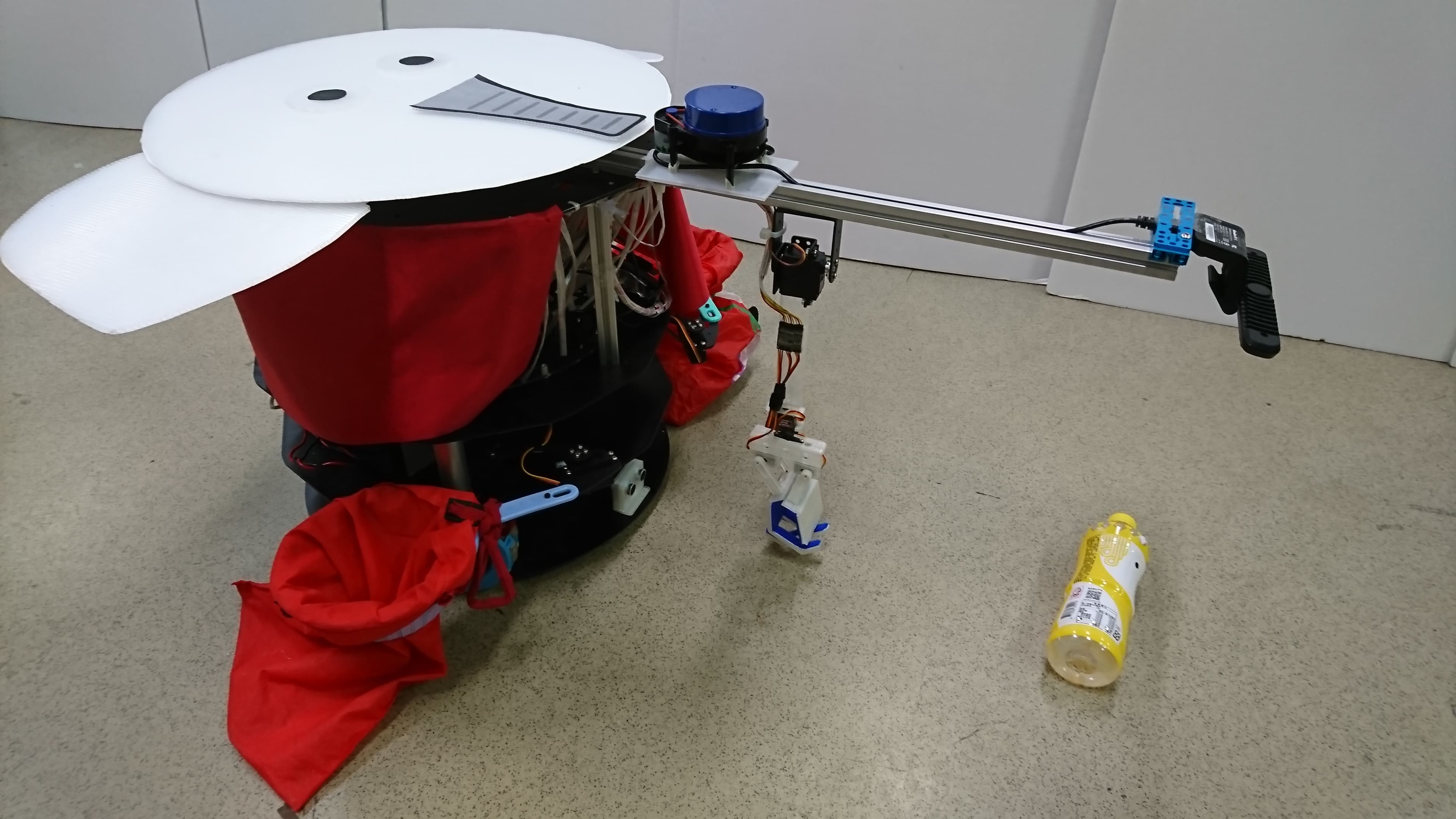
Fig. 1-1 The proposed robot
System Block
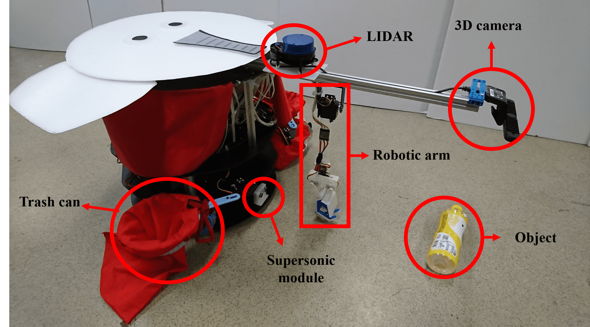 Fig. 2-1 The proposed robot
The system uses DE10-Nano software and hardware. The software include OpenCV, OpenCL, C++, Deep learning, AlexNet. The hardware include robotic arm, supersonic module, YDLIDAR, DC motor controller.
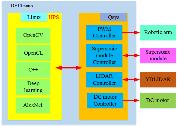
Fig. 2-2 System Block
DE10-Nano
1.DE10-Nano Development Board · Support for IntelOpenCL SDK. The DE10-Nano OpenCL Board Support Package (BSP) contains required resources for users to develop OpenCL project based on DE10-Nano Board.
2.The DE10-Nano Development Kit presents a robust hardware design platform built around the Intel System-on-Chip (SoC) FPGA, which combines the latest dual-core Cortex-A9 embedded cores with industry-leading programmable logic for ultimate design flexibility. Users can now leverage the power of tremendous re-configurability paired with a high-performance, low-power processor system. Intel’s SoC integrates an ARM-based hard processor system (HPS) consisting of processor, peripherals and memory interfaces tied seamlessly with the FPGA fabric using a high-bandwidth interconnect backbone. The DE10-Nano development board is equipped with high-speed DDR3 memory, analog to digital capabilities, Ethernet networking, and much more that promise many exciting applications.
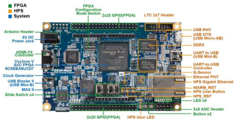 Fig. 3-1 DE10-Nano
OPENCL
An OpenCL project consists of OpenCL Kernel and Host Program. The Kernel is realized on the FPGA part of SoC FPGA. The Host Program is not the ARM part of the SoC FPGA. It is cross-compiled by Intel SoC EDS installed on Windows or Linux. The Kernel is developed in Quartus and OpenCL SDK is installed on Windows or Linux.
The system includes DE10-Nano, robotic arm,Ultrasonic module, RIDAR, Omni wheels, and UP-board. It architecture is shown in the picture 1 and described as following :
The system can recognize the bottle from a depth image. The depth image is acquired from an Intel RealSense3D Camera connected to an UP Board2 via USB 3.0.A HTTP Server is established on the UP Board2. The depth imagesof the bottle is snapped and stored in HTTP Server. We use DE10-Nano to complete the following task: (1) Get image filesfrom the HTTP Server for image processing and object recognition. (2) LIDAR and Ultrasonic module controlling for obstacle detection and collision avoidance. (3)DC motor with omni wheels controllingfor moving in all directions. (5) The 4-axis robotic arm controllingfor pick up the objects to corresponding recycle trash can.
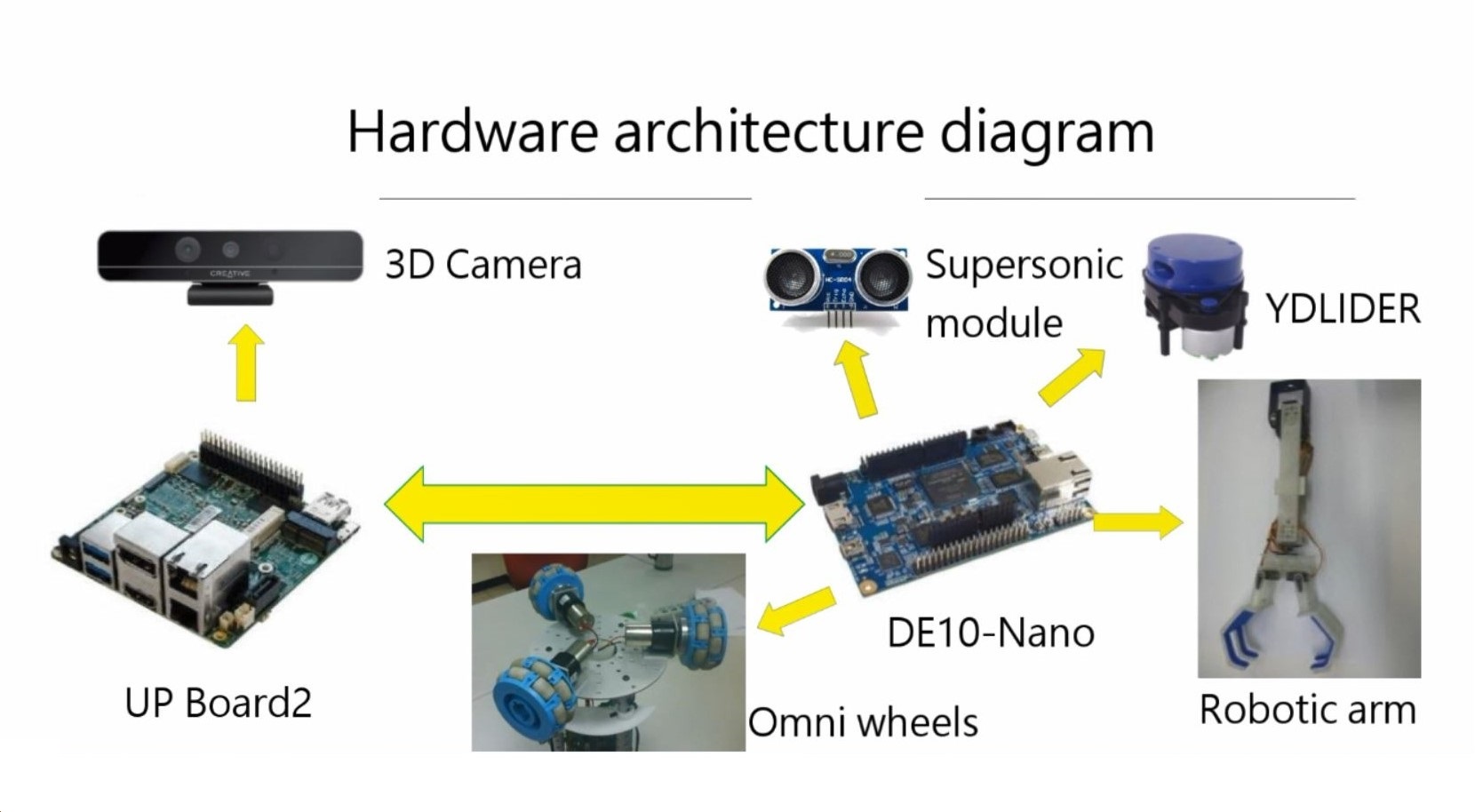
Fig. 4-1 Blocks picture
Intel realsense F200
Intel RealSense F200 has three types of lens: 1. Traditional RGB lens 2. Infrared lens 3. Infrared laser projector. The traditional RGB lens photographed frontal scenery. This image is a 2D imagery. The system combination with an infrared laser projector and infrared lens can detect the infrared reflection in front of the camera. With this measure that can understand the important message fo depth. The measures range from 20 cm to 120 cm and requires USB 3.0 port.
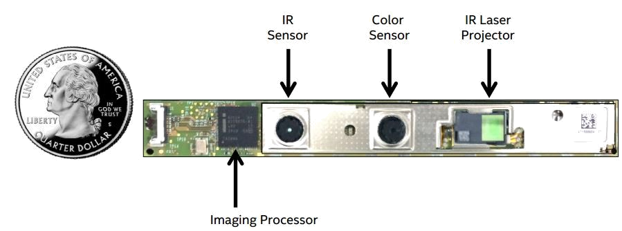
Fig. 4-2 Intel Realsense F200
UP board
The UP Board can span both Linux & Windows operating systems and has a USB 3.0 port. Even can do the network is upgraded to Giga speed.
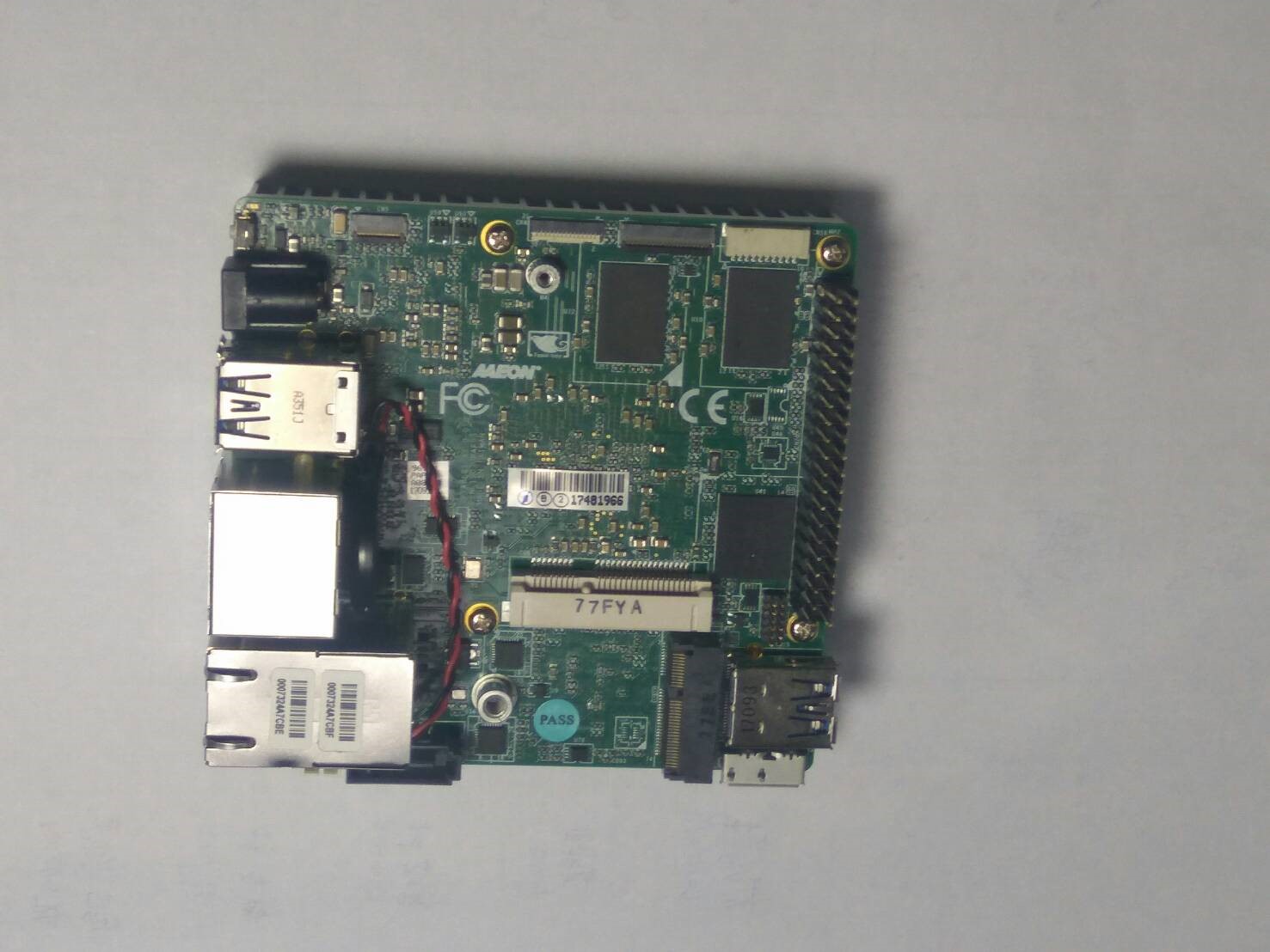
Fig. 4-3 UP Board
Robotic arm
The 4-axis robotic arm includes one MG996R and three MG90S servo motors. The MG996R is used for high torque. The entire structure of the robotic arm is made from 3D printed parts.
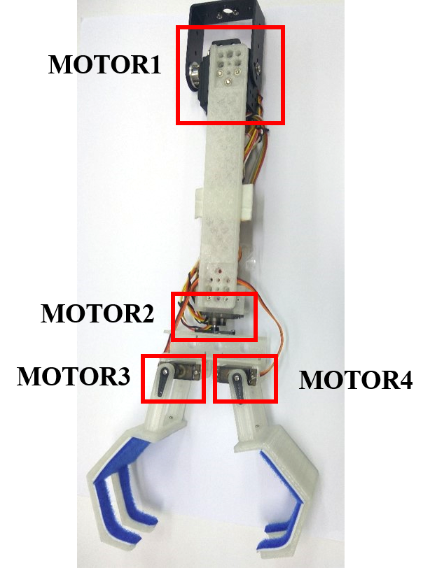
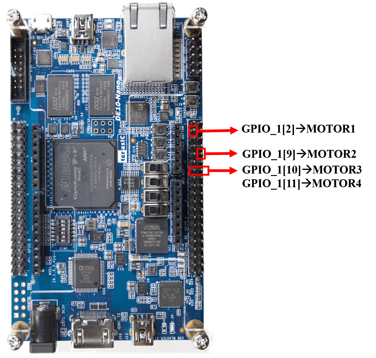
Fig. 4-4 Robotic Arm & pin diagram
Trash can
The system includes two trash can. The trash includes one MG996R servo motor.
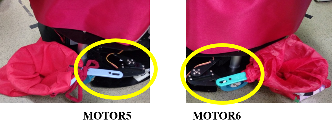
Fig. 4-5 Trash can
.png)
Fig. 4-6 Trash can & pin diagram
YDLIDAR
The YDLIDAR X4 360° Laser Scanner has a complete set of USB ports, as well as a SDK open source software. X4 uses a USB cable to connect to the computer. It is Plug and play, no need for extra coding work before use.YDLIDAR X4 low power infrared transmitter conforms to the Class 1 laser safety standard and reaches the human eye safety level. The scanning range of X4 is 10 meters. It perfectly meets the demands of various service roots, home robot and makers.
The communication frame consists of data packet header, packet type, Number of samples, Start angle, Stop angle, Check code, and Sampled data. It is mainly used for uploading information and fault information of the measurement external frame by the YDLIDAR. The valid data can be extracted from the communication frame, and not response.
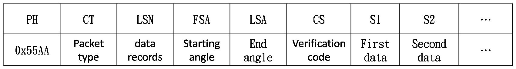
Fig. 4-7 Byte offse
Packet header: The length is 2B, it is fixed to 0x55AA, the low position is in front, and the high is in the rear.
Packet types: Represent the type of the current packet; the 0x00: point cloud packet 0x01: zero bit packet.
Number of samples: Denotes the number of sampling points contained in the current packet;The zero bit data packet has only 1 zero loci data, The value is 1..
Start angle: The angle data corresponding to the first sampling point in the sampled data.
Stop angle: The angle data corresponding to the last sampling point in the sampled data.
Check code: Check code for current packets, using double bytes or checking current packets.
Sampled data: The sampling data of the system test is the distance data of the sampling point
YDLIDAR scan range:0.12m~10m
communication method :UART 128000
Pin diagram
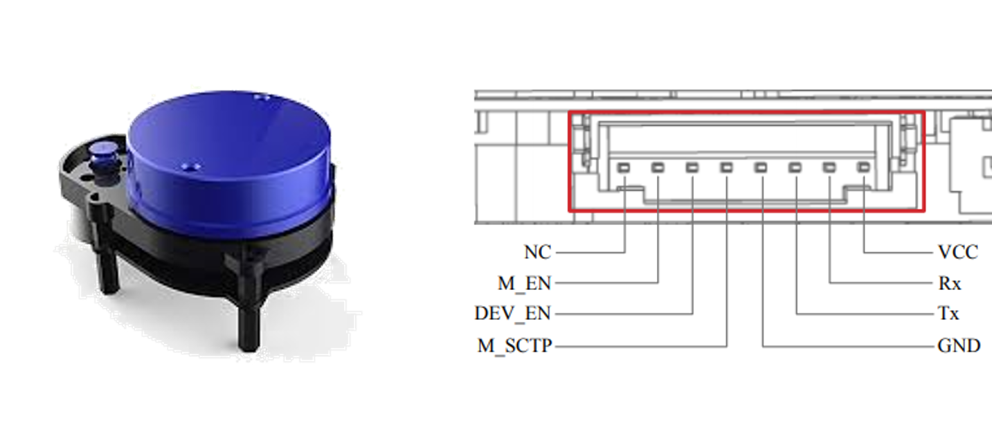
Fig. 4-8 YDLIDAR & pin diagram
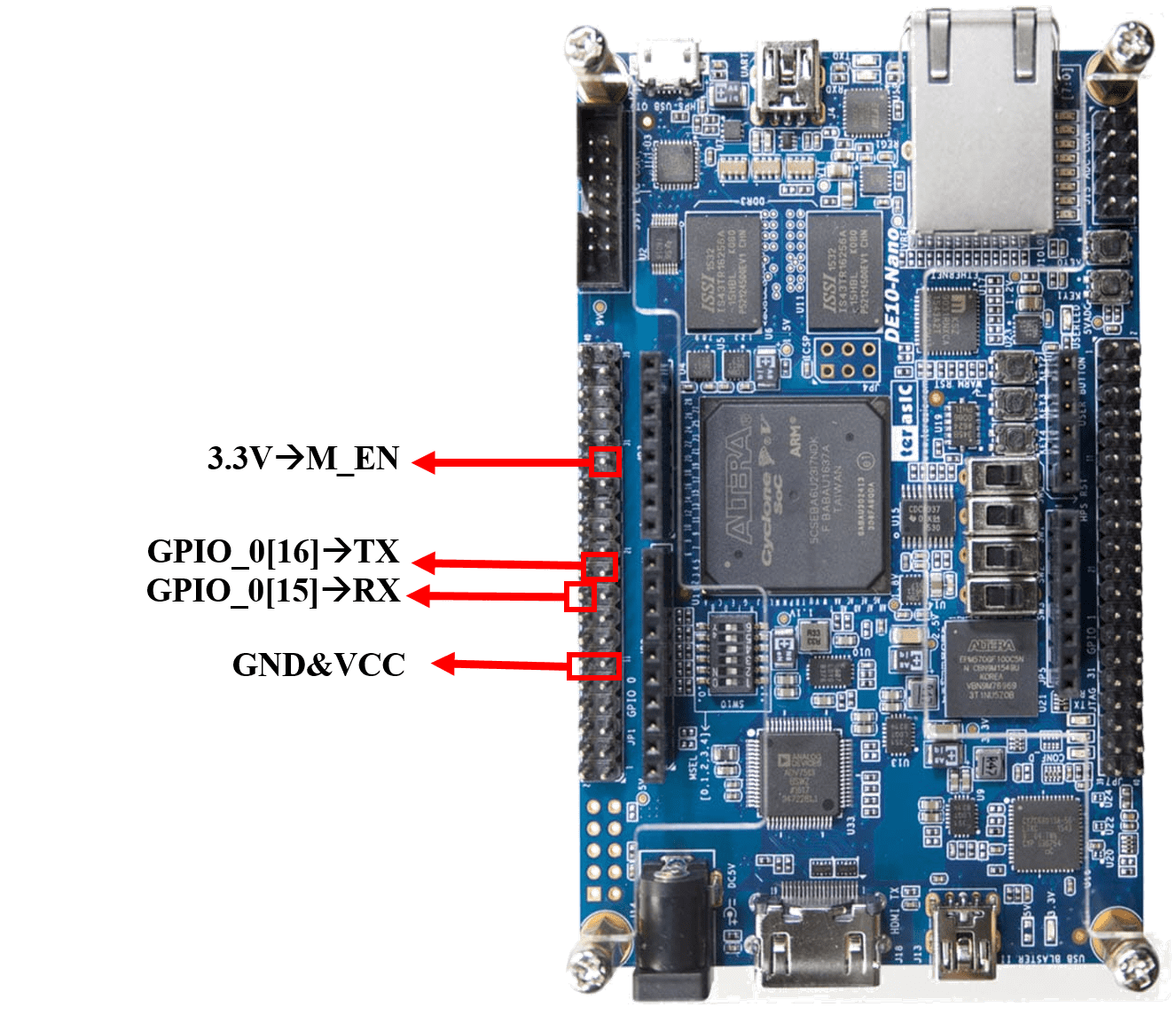
Fig. 4-9 YDLIDAR pin diagram
Supersonic module
The module works on the natural phenomenon of ECHO of sound. A pulse is sent for about 10us to trigger the module. After which the module automatically sends 8 cycles of 40 KHz ultrasound signal and checks its echo. The signal after striking with an obstacle returns back and is captured by the receiver. Thus the distance of the obstacle from the sensor is simply calculated by the formula given as Distance= (Time x speed)/2.Here we have divided the product of speed and time by 2 because the time is the total time it took to reach the obstacle and return back. Thus the time to reach obstacle is just half the total time taken.
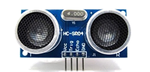
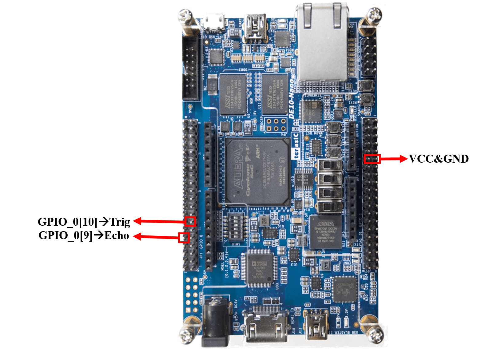
Fig. 4-10 Supersonic Module & pin diagram
We can monitor the system on webpages.
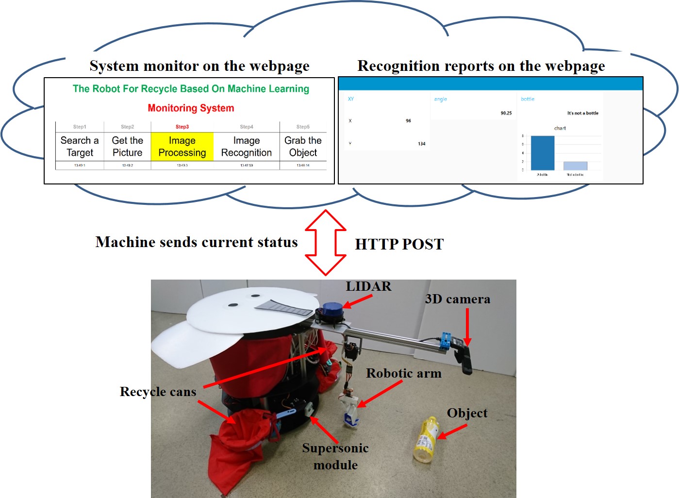
Fig. 4-11 Web page for monitor
Features
The system can recognize the bottle from a depth image.
(1)The system use the 3D Camera to do deep learning and object recognition.
(2)The system can distinguish the bottle from not bottle.
(3)The object center of gravity can be calculated using image processing.
(4)Thus, the robotic arm can grab object to the corresponding recycle trash can.
(5)Three Omni wheels are used for omnidirectional move.
(6)The robot system uses a YDLIDAR and Ultrasonic module to observe the environment
and to support robot abstacle detection and collision avoidance.
Image process get the center of gravity object.
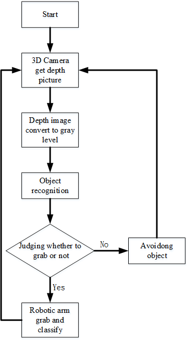
Fig. 5-1 3D Image Process Object Center of gravity Pragramming
Step1: 3D camera get the depth image.
Step2: Depth image convert to gray level image.
Step3: Histogram add up gray level image.
Step4: The gray image use Otsu algorithm to get the best threshold.The best threshold to do thresholding.
Step5: If threshold point of gray level is more than the quarter of max point . when the condition holds ,the maxvaule equal threshold and go to step 4 .
Step6: According to maxvaule decides the threshold function.
Step7: Threshold image run the convexhull function that can convex area of black.
Step8: To judge all of the area match the condition
Step9: If more than one,we choose the bigger area to be the best rectangle.
Step10: The best rectangle calculate center of gravity.
PIPCNN
CNN computations are mainly accelerated by GPUs with high power dissipations. PipeCNN is an open-source OpenCL-based FPGA accelerator for convolutional neural networks. A performance cost scalable hardware architecture with efficiently pipelined kernels was proposed.
Experimental results
The 3D Camera is 40 centimeters distan from the ground.And the 40 centimeters distant convert to 256 gray level.The distant and gray level are in direct proportion.
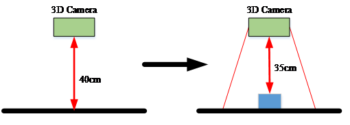
Fig. 5-2 3D camera
We use the bottle to test. The image have RGB image and depth image. Than, convert image to gray level image.
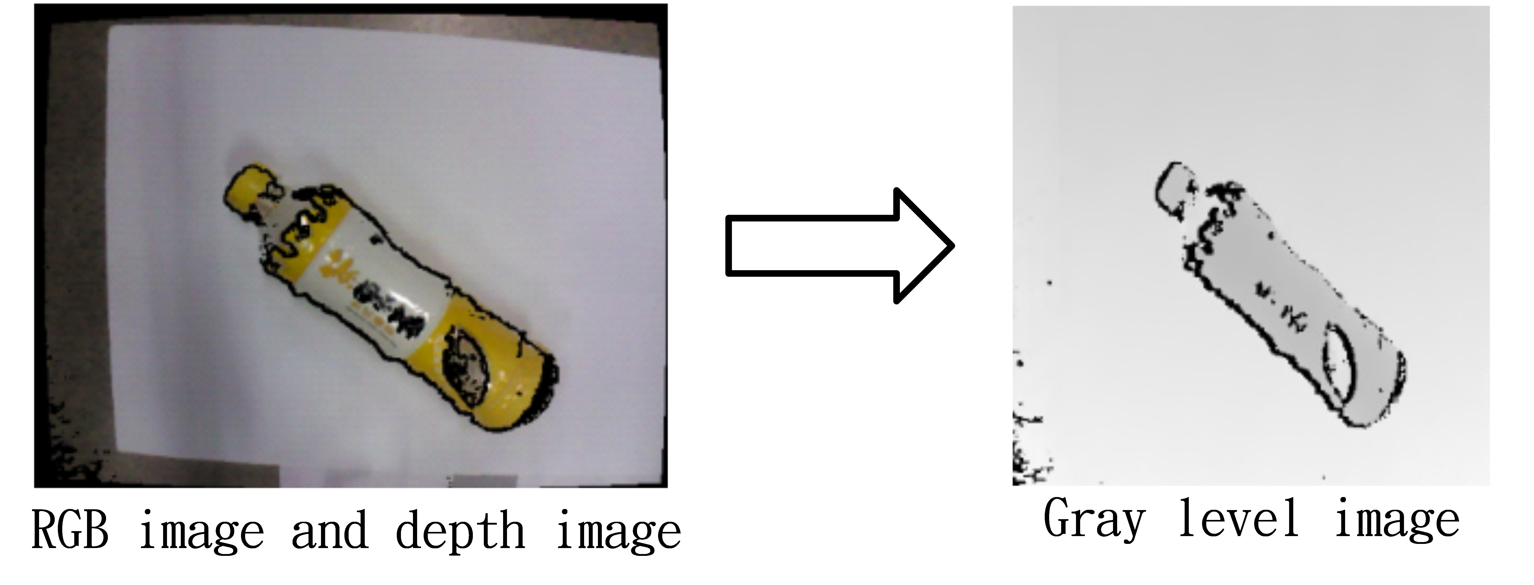
Fig. 5-3 Depth image convert to gray level image
Deep learning recognition bottle and not bottel
Object recognition performed by deep learning. Currently adopt AlexNet deep learning framework is used to perform operations and comparisons will presentation similarity objects are then used.
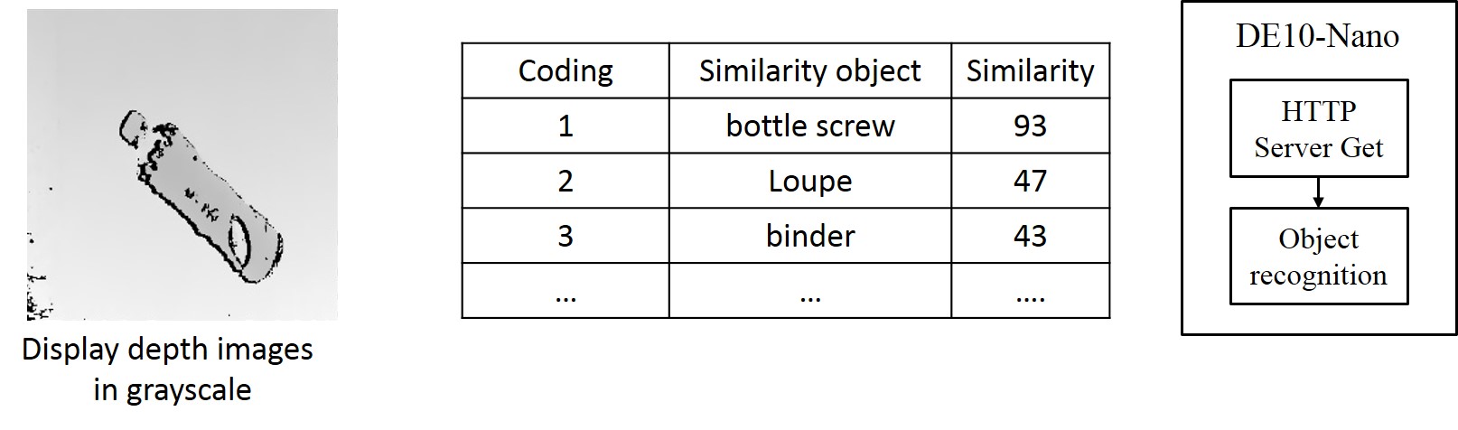
Fig. 5-4 Deep learning recognition bottle and not bottle
The system image process have 3 steps.
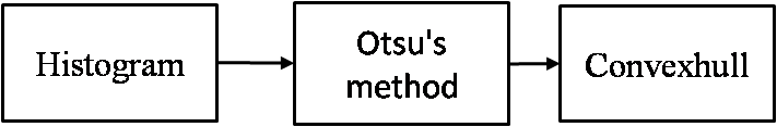 Fig. 5-2 Image Process Programming
Step1: Histogram add up gray level.
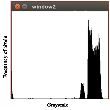
Fig. 5-5 Histogram
Step2:The gray image use Otsu algorithm to get the best threshold.The best threshold to do thresholding.
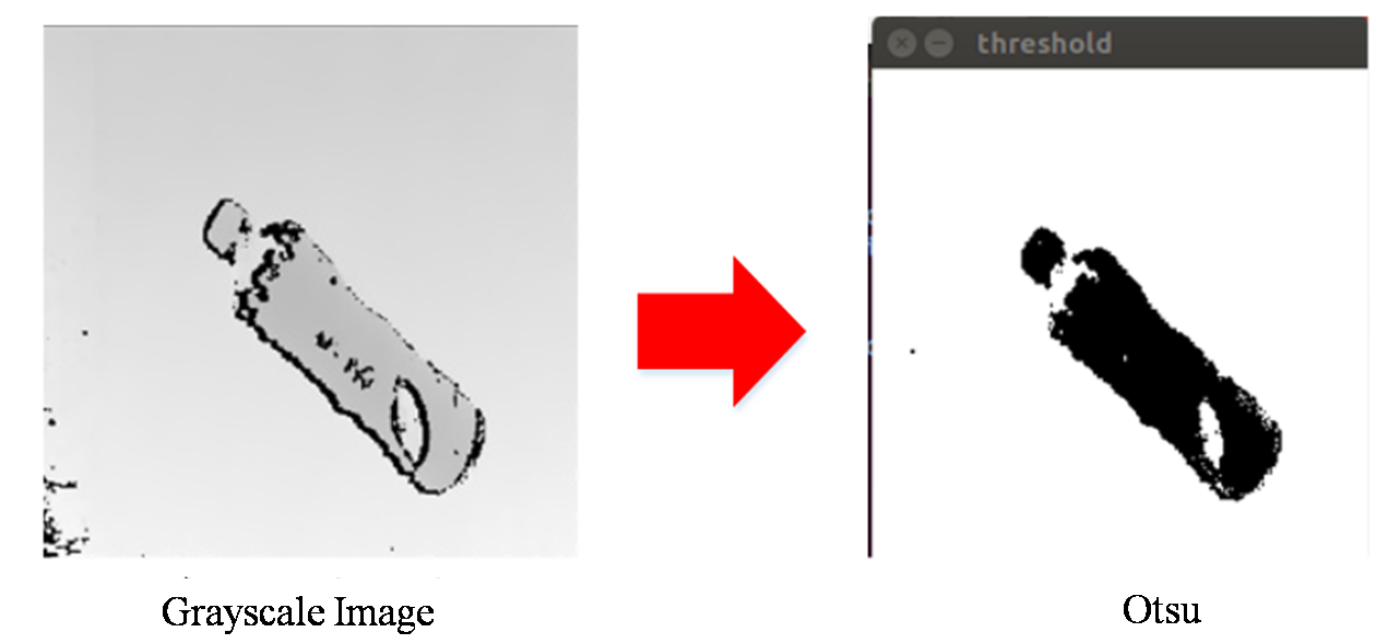
Fig. 5-6 Otsu
Step3:The thresholding image use convexhull algorithm to get the best rectangle.We can get center of gravity the best rectangle.
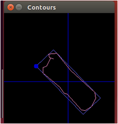
Fig. 5-7 Convexhull
Object recognition
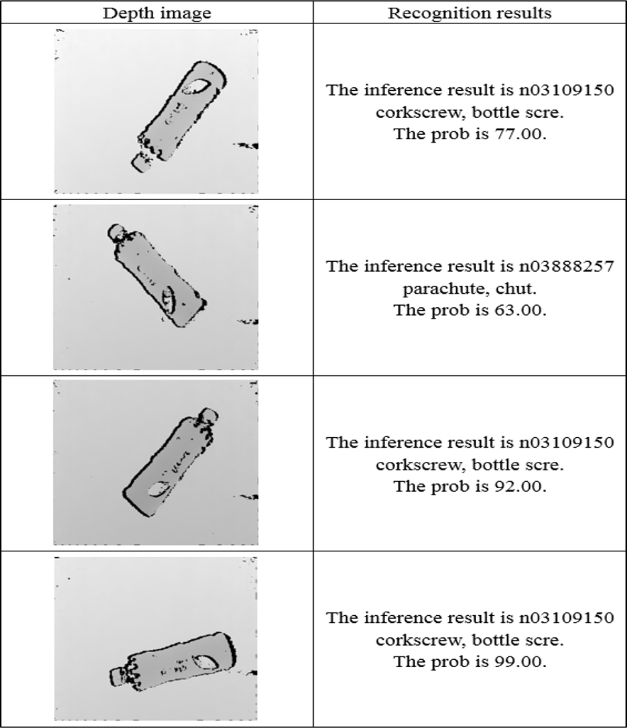
The system can recognize the bottle from a depth image.
Table. 5-1 Object Recognition results
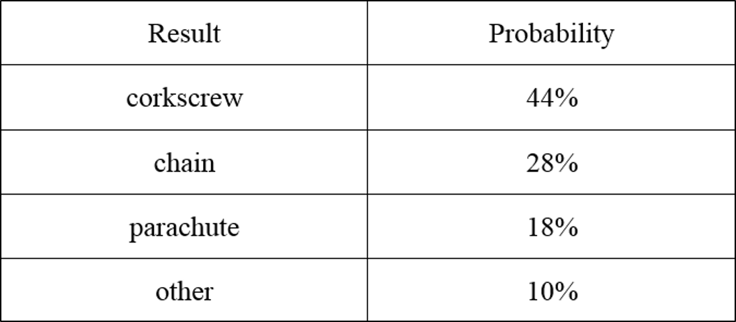
We get the results to calculate and analyze.We can find that corkscrew 、chain and parachute chance of occurrence is top three in the results.
Table. 5-2 Experiment statistic results
System Flow chart
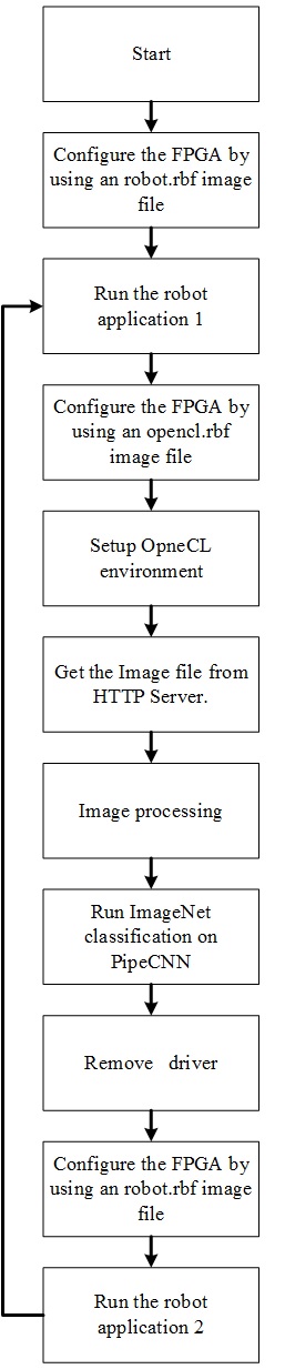
Fig. 5-7 System Flow chart
Flow Summary
The following picture is our compilation report this project used 17 percent of logic elements, and almost 8000 registers are used. A large percentage of registers are for filtering the noise of binary image. Besides we used lesst then 1 percent (2816 Kbits) of embedded memory in DE10-Nano. To sum up, there are still a lot of space on the board and it shows the high capability and integration level of embedded FPGA board.
.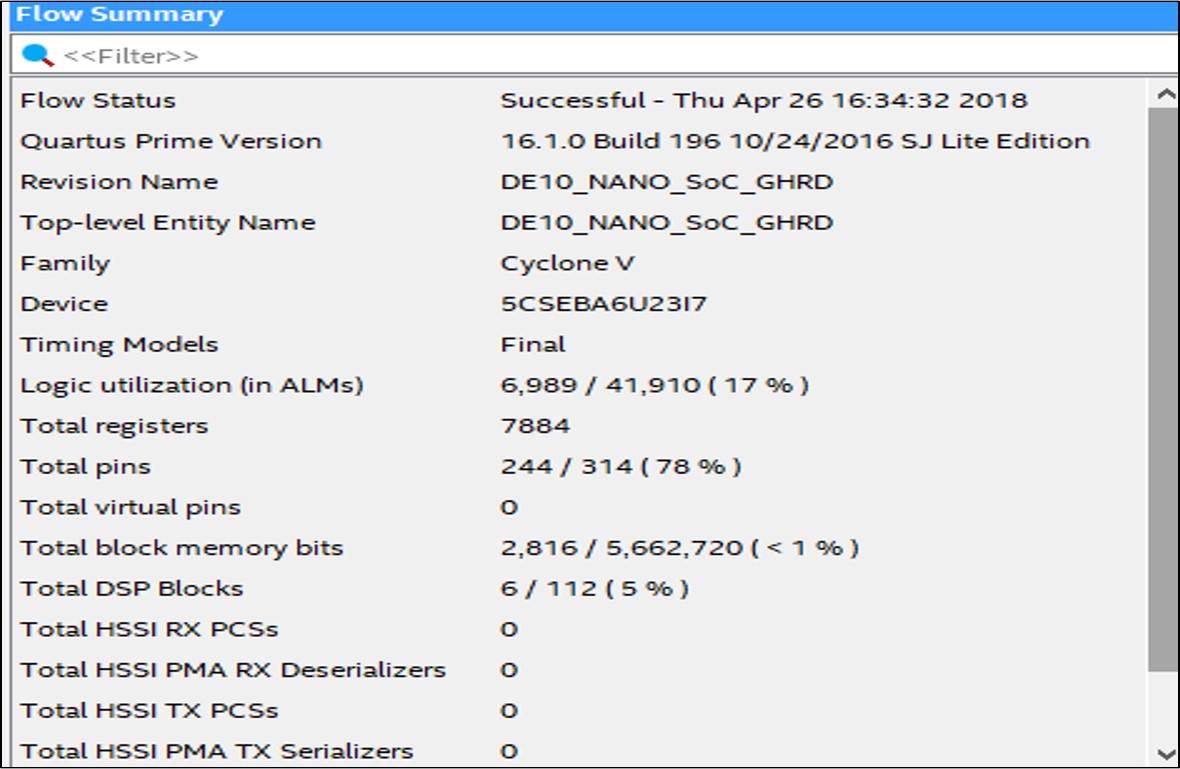 Fig. 6-1 Performance Parameters
HPS
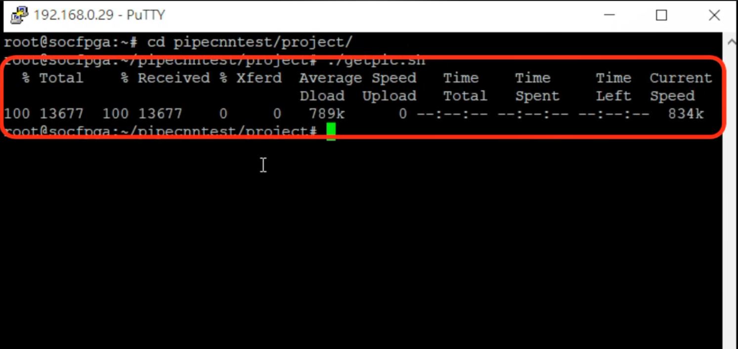
Fig. 6-1 Http servor
The object center of gravity
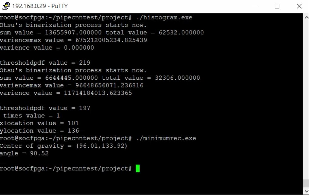
Fig. 6-2 The object center of gravity
Recognition bottle or not bottle
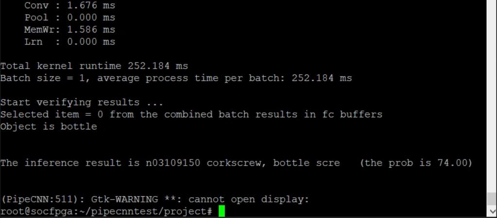
Fig. 6-3 Recognition bottle or not bottle
Features
The system can recognize the bottle from a depth image. (1)The system use the 3D Camera to do deep learning and object recognition.
(2)The system can distinguish the bottle from not bottle.
(3)The object center of gravity can be calculated using image processing.
(4)Thus, the robotic arm can grab object to the corresponding recycle trash can.
(5)Three Omni wheels are used for omnidirectional move.
(6)The robot system uses a YDLIDAR and Ultrasonic module to observe the environment and to support robot obstacle detection and collision avoidance.
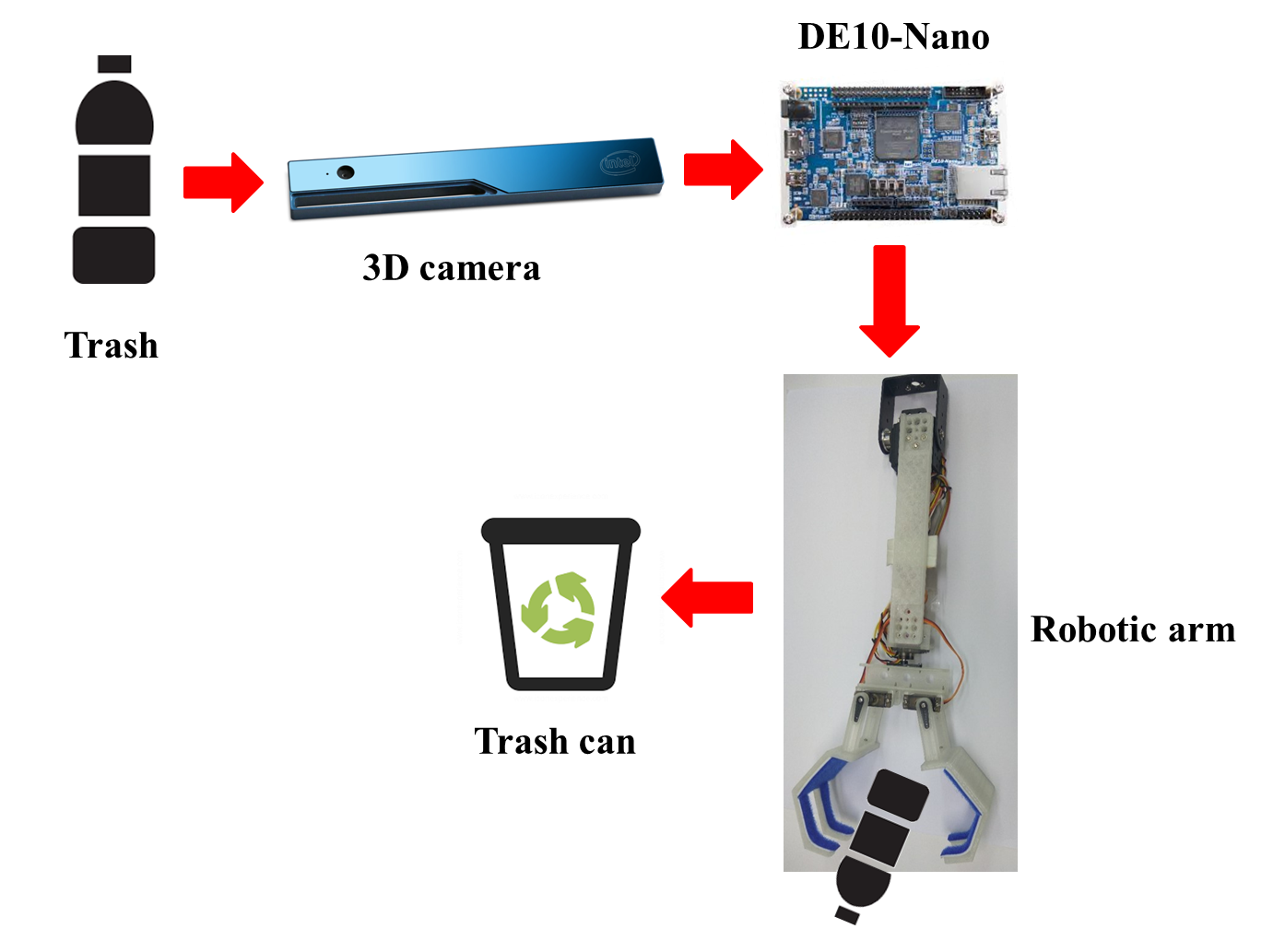
Fig. 7-1 System programme
Summary
The system use deep learning do distinguish object. Our deep learning image from 3d camera depth image data. The system can distinguish the bottle from not bottle. The object center of gravity object can be calculated using image processing. Thus, the robotic arm can grab object to the corresponding recycle trash can. The robot system uses a LIDAR and Ultrasonic module to observe the environment and to support robot obstacle detection and collision avoidance. Three Omni wheels are used for omnidirectional move.