PR075 » 肖像写真器
设计意图:
肖像画是一种描绘具体人物形象的绘画。绘制肖像画并不是人天生的本领,需经过长期的训练,艺术家才能绘制出非常逼真的肖像画,而且人工绘制肖像精力有限,绘画时间长,因此设计一个肖像写真器可以让普通人即使不懂绘画也能得到一幅肖像画,增添了生活的趣味性。
设计思想:
为了能让机器人画出写实的肖像画,首先必须由计算机自动生成人脸的线条画,因此,我们采用基于机器视觉的方法,结合人脸检测和人脸特征提取等技术,设计如何把人脸中的特征轮廓线提取出来,转换为矢量点,作为机器人移动绘画的轨迹。
Portrait photo device
一. Design Overview
1.1 Plan for design
Portrait painting is a kind of painting depicting a specific figure. Whether in China or in Europe has a very long history, in China can be traced back to the Western Han Dynasty portraits until modern times, is still a very popular form of artistic expression. We can see street artists drawing portraits from time to time on the street. However, drawing portraits is not a person's natural ability. After a long period of training, artists can draw portraits that are very realistic, and the manual drawing of portraits has limited energy and drawing time. Therefore, designing a portrait genre can make ordinary people understand Painting can also get a portrait, adding to the fun of life.
1.2 Application and target users
The portrait genre can be used in commercial plazas to attract tourists and can be displayed in schools so that contemporary youth can have a deeper understanding of modern technology. The portrait photo device can accurately design the human facial features so as to compare with the characteristics of the lost elderly children and the fugitives, thus improving the chances of sulking other people's faces.
Machine vision-based portrait-rendering robots are high-tech robots that combine technology and entertainment to show the public the benefits of machine vision and robot motion control. Portrait drawing robots can be used in science and technology museums such as the Children's Palace and other exhibitions. They can educate teenagers and popular science enthusiasts about science knowledge and stimulate their interest in science and technology.
Today, with the rapid development of science and technology, intelligence is ubiquitous in human life. In the future, intelligence can also be added to the portrait writer, and it will be widely used in various aspects of life in the future. For example, drawing a portrait to highlight its five features helps to filter and monitor sensitive people during exit and entry management, compare the suspect's photos, and compare the identity of the user in the field of human-computer interaction to automatically identify the user's identity for system login, etc. Access control systems for confidential departments and information systems, authentication of financial users and electronic commerce, etc.
二. System solutions
Machine Vision is one of the key technologies of portrait robots. A complete machine vision system first collects the image information of the target through the image acquisition device and then passes it to the image processing system. The image processing system will process the image information according to a certain algorithm and make corresponding control actions according to the results.
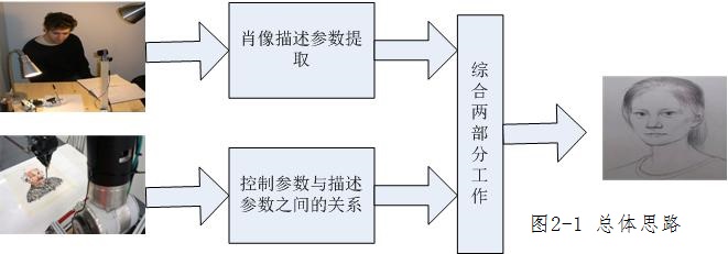
2.1 General idea
In order to make the robot draw realistic portrait painting, the line drawing of the face must be generated automatically by the computer. Therefore, we use the method based on machine vision, combine face detection and face feature extraction, and design how to extract the feature contour in the face and convert it into a vector point, as a robot moving painting. The track.
2.2 hardware module
The selection and design of the hardware system. It includes selecting mechanical arm according to functional demand, structural design of mechanical arm and brush connecting part, overall system layout design, and image acquisition system type selection.
Image acquisition and extraction algorithm: using the selected image acquisition system to capture the audience's face image in real time, save and extract data from it.
The algorithm of face contour extraction includes the decomposition of YCBCR color space images, the iterative threshold method, the optimal segmentation threshold, the contour segmentation algorithm, the contour extraction algorithm, the face feature extraction algorithm, the collar contour extraction algorithm, the hair removal algorithm, the eye and eyebrows location and optimization extraction algorithm design.
Robot arm painting control system: vectorization of face contour pixels, painting action planning algorithm, manipulator control design.
三、Design features
3.1 Image acquisition
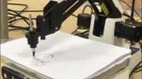
The camera is connected to the expansion board to be photographed, the expansion board is combined with the FPGA development board, and the hardware description language of the development board is used to control the operation of the photographing and saving pictures of the camera, and a continuous mode is chosen, and a buffer is defined to save the image data.
3.2 Feature of portrait data
Comparing the principles and characteristics of the commonly used color space, we choose YCbCr color space for skin color modeling, and use iterative threshold method to carry out skin color segmentation.
The internal hollowing method is used to extract the outline and scan the pixels line by line. When the black pixel is encountered, first read the pixel value of its eight neighborhood points, save it in the array, and then calculate the sum of the array. If it is 0, the eight points are all black, and the center point is set to 255 white, or else the next point is re scanned.
The search based projection method is used to locate the eyes and eyebrows, and the search algorithm of the eyes and eyebrows is extracted by removing the noise, and the face contour is optimized to improve the overall effect of the face image.
Based on the vectorization algorithm of eight domain search without interference, the pixel points of the face contour are converted into a series of connected points, and then the points on a straight line are detected in each of the points connected by each group, and the first point coordinates of the line segment are kept in the array, so as to prepare for the communication of the manipulator controller.
3.3 Parameter control and description
The five features extracted by the image description parameter system are located on the XY axis to form a single pixel point. Through the vectorization processing of the mechanical control system, a series of points are converted into vector lines, and the contour maps are formed at the end.
The connection controller of the mechanical control system can realize the external control manipulator by solving the automatic communication between the external coordinates and the internal variables: the drop - drawing - pen.
1、General idea map
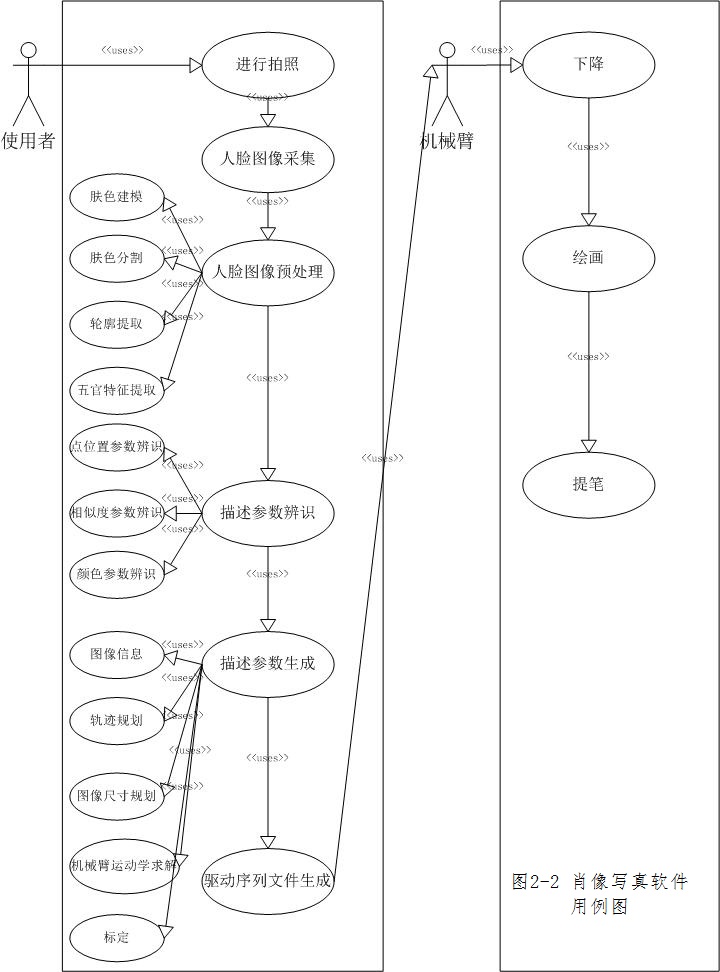
2、Use Case Diagram
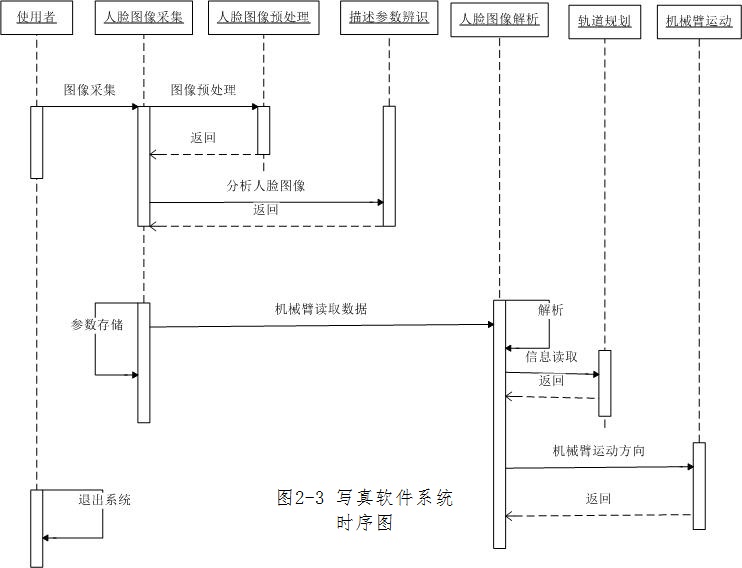
3、ime sequence diagram
Machine vision (Machine Vision) is one of the key technologies of portrait robot. A complete machine vision system first collects the image information of the target through the image acquisition device, and then passes it to the image processing system. The image processing system will process the image information according to a certain algorithm and make the corresponding control action according to the result.
Because of the pixel problem of the ordinary camera, it is difficult to mask the skin defects and burrs of the parties even by the mapping software, but the portrait photo device can draw the user's outline and the exquisite features of the five senses in the case of less skin quality. Artificial portraits are limited, painting time is long, and it is impossible to accurately determine the features and location of the facial contour of the painter, but the portrait device is not fatigued and accurately draw a portrait within a specified time.. Portrait portraits can be used in commercial squares to attract tourists and to exhibit in schools, so that contemporary youth can have a deeper understanding of modern technology. Portraiture can be designed to make a precise design of the five senses of the human body, so as to compare the appearance of the lost children and the suspects in the escape, so as to improve the probability of screening human faces.
A. Photograph
|
Fig.1 System block diagram |
The design module is a dual port RAM control module, which can control on-chip memory and read and write image data. The original data of the camera will be first written to the RAM on the chip. After completing the writing of a frame, the on ChIPHFRAM module reads the data from the dual port RAM to the RAW2RGBJJ module to transform the original data into RGB data. The RGB data will be output to the LCD together with the timing of the signal generated by the VGAX controller, as shown in figure Fig.2 The usb-blaster port of the camera and the PC connection of the de10-nano board connect the HDMI interface monitor to write the sof file of RTL into the de10-nano board to run the test program screen and appear on the monitor screen like figure Fig.1. At this stage, we have completed the function of reset and focus of the lens, and the characters will be completed at the later stage.
Fig.1 System block diagram

Fig.2 A camera connection
B. Contour extraction.
In contour extraction, we use the edge detection method. The essence of edge detection is using some algorithm to extract the intersection line between object and background in the image. We define the edge as the region boundary with sharp change of gray level in the image. The change of image gray level can be reflected by the gradient of the gray distribution of the image, so we can use the local image differentiation technology to get the edge detection operator. In order to minimize the impact of noise on edge detection results, noise must be filtered to prevent error detection caused by noise. In order to smooth the image,the Gauss filter is used to convolution with the image. This step will smooth the image to reduce the obvious noise influence on the edge detector.


Fig.3 Original map Fig.4 Edge detection effect map
C. Manipulator drive
In the extraction of the section of the portrait line, we mainly use SVG to make a vector graph to ensure the image quality of the contour extraction. After the analysis, we convert the SVG into the PTP instruction to drive the robot arm drawing, and then the picture is generated.
In the communication part, we use the communication protocol between the command / data interaction between the Dobot arm and the upper computer. The communication protocol is controlled by the DE10-SOC development board. The data received every time in the physical layer of the USB is controlled by the USB to control the physical layer. The communication protocol is needed to determine the beginning of the data and the veracity of the data. Communication protocols generally need data packets including Baotou, data load, load test and so on to ensure the accurate transmission of data.
Advanced stage
A. Algorithm
At the advanced stage, we will also take a side view to recognize faces, and imitate them at any angle. In face recognition, we will locate faces based on facial features (such as eyes, nose tip, lip, etc.). After the feature extraction, you can start from any part of the picture, such as starting from the nose first to complete the portrait of the portrait; at the same time in the SVG to PTP algorithm will also improve, improve the photo rate.
B. Hardware
We consider making full use of the advantages of FPGA to realize the multi-channel PWM driving mechanical arm steering gear and complete the communication function with the main board DE10-SOC.
C. Deformation
At the advanced stage, we use a three dimensional radial basis function to control the deformation of the target image by a predefined handle to make the face achieve a fat and thin effect, and use a triangular mesh to subdivide the surface to make the portrait surface smooth.
The maximum extension distance of the robot arm is 320mm, and the repeatability positioning accuracy is 0.2mm. The picture is realistic.

Fig.5 Mechanical arm
The Dobot Magician manipulator has two modes of motion: one coordinate control mode and two single axis control mode.
Coordinate system control mode: the manipulator arm coordinate system, as shown in Figure 2-1, is the focus of a large, small arm, and the base of three motor three axes, the X axis is perpendicular to the fixed base, the Y axis is perpendicular to the fixed base and the Z axis is perpendicular to the right rule.
Single axis control mode: at this point, the target objects of the manipulator are independent axes. When the button is pressed according to the corresponding button, the independent rotation of the shaft corresponding to the robot arm is stopped. The axis is in the direction opposite clockwise. The Joint1, 2, 3 and 4 on the interface correspond to the control of four independent revolving axes of the base, the arm, the arm and the head steering gear respectively. In this work, the head is a fixed writing tool, and no head steering gear is used.


Fig.6 Coordinate axis controls Fig.7 single axis control
D8M-GPIO is a 8 million pixel camera kit for 2x20 pin GPIO connector interface. Support focus control.

Fig.8 Camera object
The design of this work is divided into 2 stages:
This stage is the initial stage. We have implemented the SVG file extracted from the corddraw software and converted it into the PTP instruction sequence. Select and select photos through web pages and drive the robot arm to write.
The portrait portraits are divided into three parts: 1. snapping characters, 2. contours, 3. mechanical arms. To capture the character and reset the character of the lens at present, the outline extraction part is mainly to extract the outline of the characters through the edge, and then generate the SVG file. The driving part of the manipulator is mainly responsible for combining the control parameters of the robot arm and the description parameters of the outline to generate the PTP command by the driver. Sequence, and then through the communication protocol to drive the robot arm to complete portrait portrait function.
In order to make the robot draw realistic portrait painting, the line drawing of the face must be generated automatically by the computer. Therefore, we use the method based on machine vision, combine face detection and face feature extraction, and design how to extract the feature contour in the face and convert it into a vector point, as a robot moving painting.


