
PR109 » 音频图像处理及其全息显示(3D Holographic Generator System of Audio Spectrum and Actual Object)
Our 360-degree holographical phantom imaging system based on SoC FPGA use audio processing technology and " pseudo holographic projection" technology to display the real time 3D image of audio spectrum and actual object. On the one hand, SoC Architecture on FPGA can realize the input and process of object image and multichannel audio. On the other hand, 3D holographic projection technology will show the three-dimensional illusion of image so people will intuitively feel the character of music rhythm and the whole picture of the object in front of the camera, creating a striking visual impact.
1:Design Goals
The advantages of 3D holographic projection technology are not only to utilize light diffraction to create a virtual three-dimensional image of an object, but also to enable viewers to see the images without any special glasses or external equipment, which means making people feel more realistic. That is to say, the convenience that people do not require 3D glasses or other wearable devices to help them see the images immerses people in the amazing 3D phantom stereo display without any bound feeling. Therefore, our system will bring you a great visual impact through both horizontal and vertical parallax. Because of the advantages of SoC Architecture on FPGA, such as low power consumption, high efficiency, powerful and flexible processing capability of multichannel audio signal, we use the Altera FPGA board as a processing platform to facilitate the design of our phantom generator system. What our system is going to do is: displaying the audio spectrum in a real time manner —— the system will update audio spectrum in a very short time, making use of an optical phenomena called the persistence of vision, viewers will see the continuous animation of audio spectrum. Besides, the system will display the item in front of the camera in 360-degree way.
2:Application areas and Target users
The design can be used in many fields. For example, 3D print designer can preview his or her design by using the device before printing. With the help of our system, designers will create delicate works more economically and more efficiently. This design will also be suitable for showing item remotely: scanning information of the item through a camera, and transmitting the information wirelessly to the receiver. Then through our system processing, the receiver will see the holographic image of the item that the sender scanned just now. Therefore, the design can be utilized in online shopping. Online sellers, who pay attention to showing their goods though images and videos, can show their goods more vivid and all-inclusive in this way. Similarly, with the design, people who shop online can get more details and better understanding of the products he will buy. This design, even can be used in video call.
In addition, the function of displaying audio spectrum takes the music-loving 's fancy. The system can be connected in all kinds of music players, giving them a new way to feel the rhythm of the music .
As shown in figure 1, the overall structure of the system is divided into two parts:
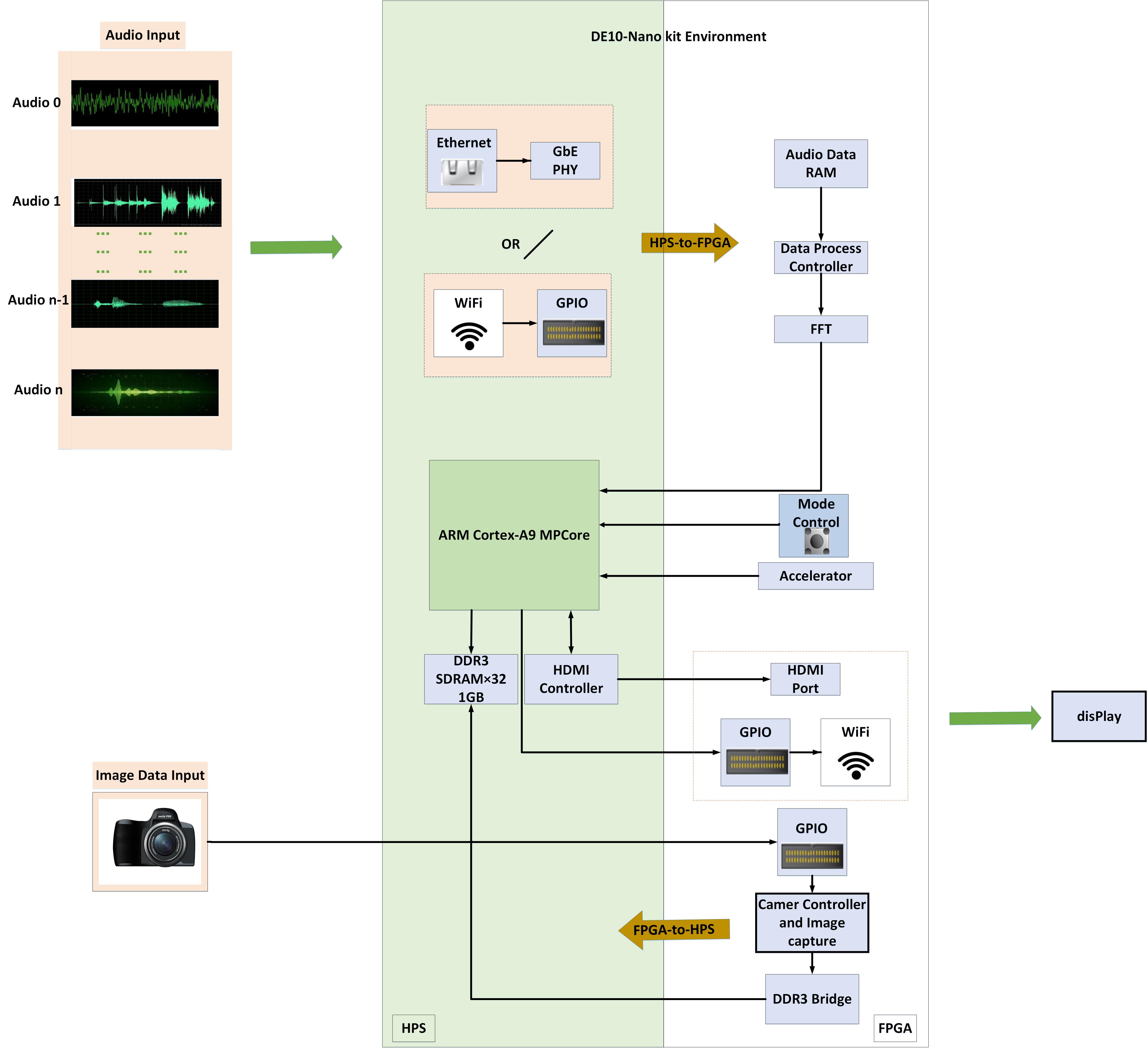
Figure.1 Structure diagram of 3D Holographic generator System
1:Data input module
The input module of the system is divided into object image data input and audio data input.
(1).Specifically, as shown in figure2, the design will capture four different directions views through camera, and transmit the image data to ARM, which is the most important role of the system. Then, ARM will process these data to relive the conversion of 2D to holographic image.
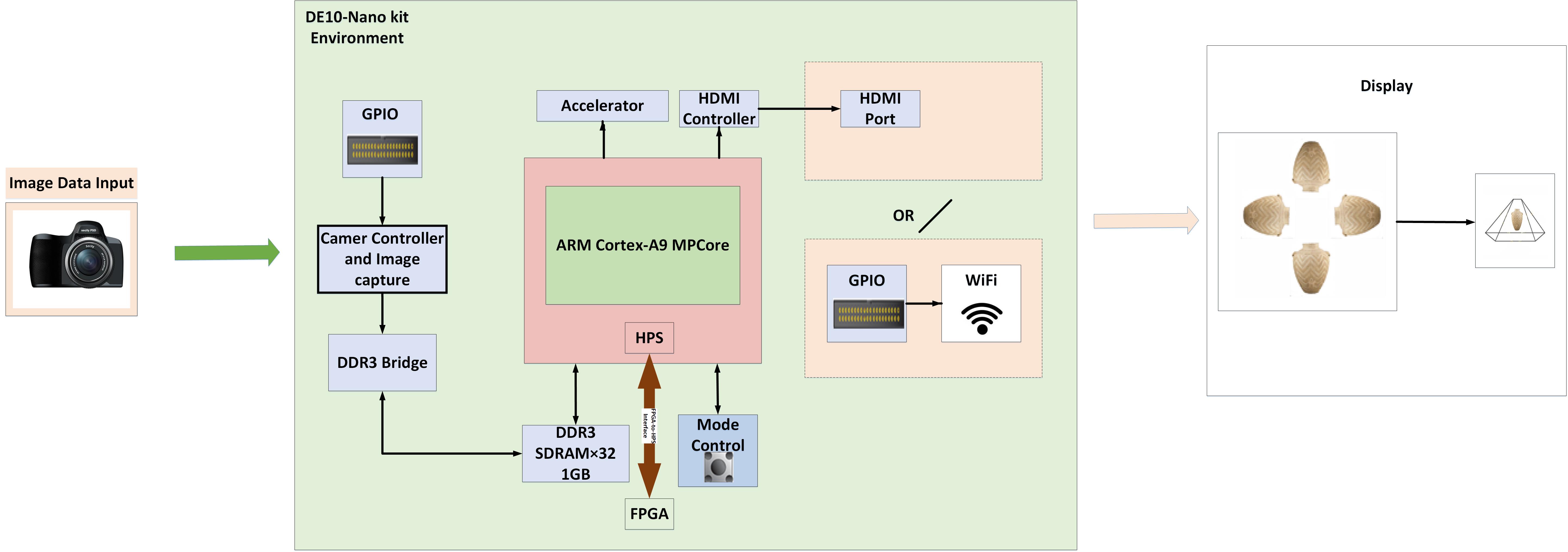
Figure.2 Structure diagram of image data input module
(2).Figure 3 shows that there are two ways can be used in the design:
①As shown in figure2, we can transmit audio input data to the device through a PC and socket connection, which sets PC as server and sets DE10 as client.
②Transmit audio input data to FPGA through extra ADC converter.
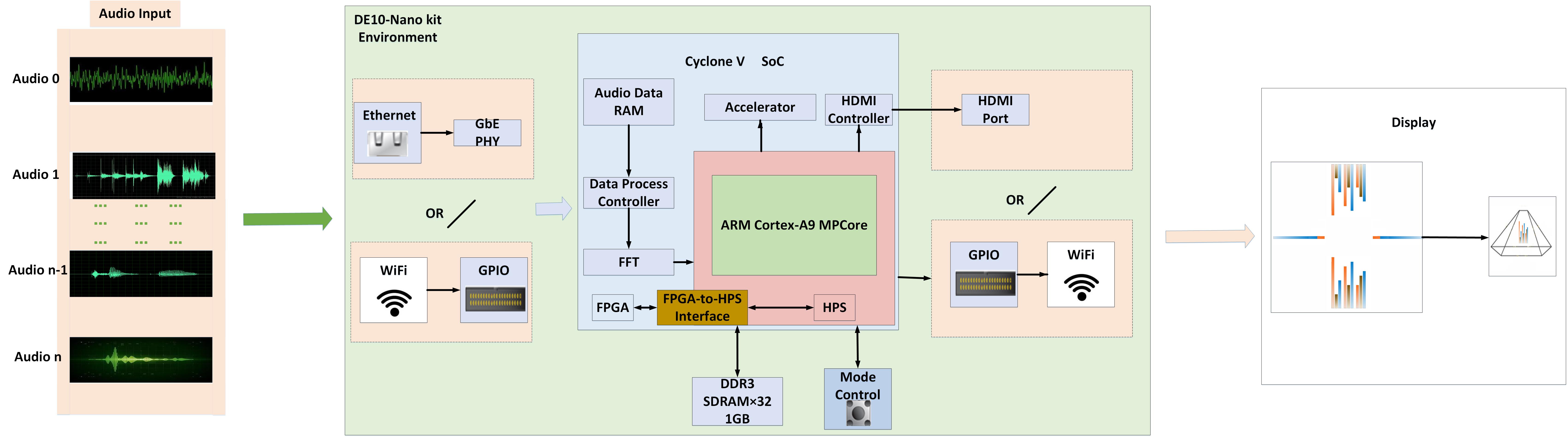
Figure.3 Structure diagram of audio data input module
2:FPGA module
(1)Make the Fast Fourier transform (FFT) of input audio data then to transmit these data to ARM for further process.
(2)Interface design, users will define the I/O interface with timing and trigger functions by themselves easily, combining the diversity of signal conditioning module with massively flexible I/O based on high performance FPGA.
Data preprocessing and post-processing, reducing the burden of real time processing application on the microprocessor, to accelerate ARM 's works.
Fourier analysis converts a signal from its original domain to a representation in the frequency domain and vice versa. And the Fast Fourier transform is an algorithm to reduce the complexity of computing the DFT from.
The FFT is defined by the formula:

Go from the time domain to the frequency domain. Figure4 is our Matlab simulation of FFT transform of an audio.
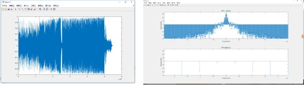
Figure.3 Simulation of FFT Transforming Audio with MATLAB
3:HPS module
ARM module is mainly to complete the functions as follows: image processing based on OpenCV; further data processing of spectrum information form the appropriate display information; Image processing of the photographic data to obtain display information of the adapted imaging system.
Open Source Computer Vision is a functional programming library for digital image processing and Computer Vision. Users can perform image processing using the OpenCV function library built into the LXDE Destop BPS. In addition. Inaddition, the chain of BPS also contains the tools needed to build OpenCV applications, so Developer projects can be developed and executed directly on the LXDE Desktop without cross-compiling. All image processing calculations are performed by ARM processors, but developers can improve the performance of key calculations through the FPGA.
4:Transmission module
The function of transmission module is to send the image data processed by ARM to the display device.The transmission module has two kinds of reference methods, divided into wired transmission and wireless transmission.
(1).The cable transmission mode is mainly through HDMI interface and communication protocol for data transmission.
(2).The wireless transmission part uses the wireless bluetooth transmission mode.
5:Display module
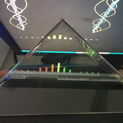
The "pseudo holographic projection" used by the display module is based on the virtual imaging principle: the virtual imaging system is a semi-aerial imaging system that suspends three-dimensional images in the real scene of the cabinet. The virtual imaging system based on the principle of spectroscopic imaging consists of the cabinet, the spectroscope, the spotlights and the video playback equipment. The system first builds a three-dimensional model of the actual product image and secondarily overlaps the captured product image or product 3D model image into the scene. This constitutes a combination of static and dynamic product display system.Visually, it looks like a holographic effect, but it's actually 2D imaging.
Figure 5 is a holographic projection imaging schematic:
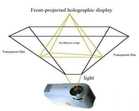
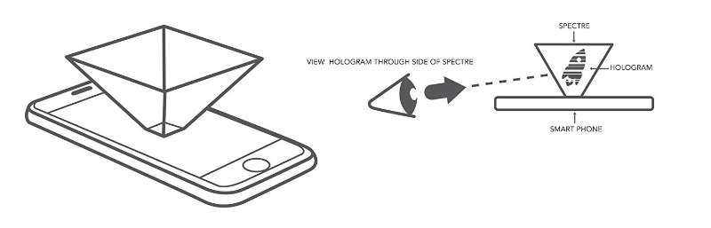
Fig.5 The schematic of Holographic projection imaging
Figure 6 is a physical display of the display device: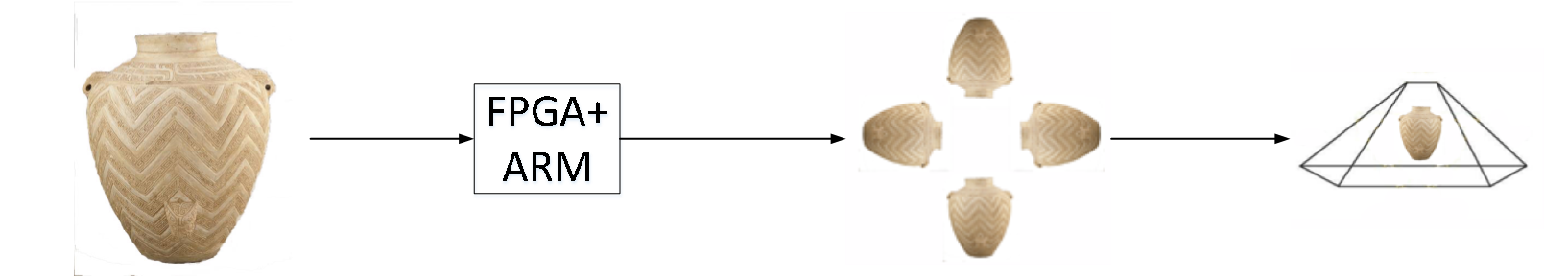
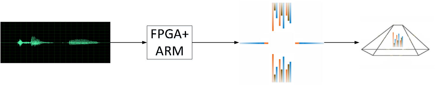
Fig.6 Reference example diagram of the display device
Design Features(Intel FPGA Virtues in Project)
1:FPGA multi-channel parallel processing capabilities
Compared with the traditional dedicated DSP, the system can process audio signals of more channels in real time, thanks to the FPGA's powerful parallel processing capability, which reflects the increasing speed advantage of FPGA in signal processing.
2:Abundant interface resources
FPGA has a wealth of configurable interface resources, which can make up for the shortcomings of the lack of ARM’s interface type, which allows users to define their own use of the interface conveniently and flexibly.
3:Flexible and low-power hardware architecture
The system architecture has a more flexible reconfigurability with more interfaces and resources at the hardware level that can achieve more functional expansion. Using programmable logic devices to complete the circuit functions, not only can meets the transmission speed required by screen system in high-speed image data transmission, but also can increase the flexibility of circuit design to shorten the design cycle and reduce the cost. The design can be based on the need of practical application to flexibly modify the appropriate hardware description language program, rather than the need to modify the circuit hardware design. Compared with software processing, with the same power consumption, this system generally has a higher performance.
4:FPGA+ARM=More power computing and control capabilities
Dual-core ARM 32-bit microprocessors solve the system control, addressing and other issues, which can support a more stable display of the bigger visual area and store more display content. Although all image processing calculations are performed by the ARM processor, we can dramatically improve the performance of critical computations through FPGA.
1.Design purpose and application scope
The spectrum analyzer display we use in daily life is always not vivid enough. For this reason, we decided to design a unique spectrum display device that displays the spectral components of audio files in the time domain and the frequency domain at the same time on the projector. Different fields can be seen from different angles. At the same time, our system can also collect front and back and left and right sides of the real object through the camera, pass the picture information to the board through the GPIO, and display the picture after the picture processing. A complete 360-degree holographic object can be seen on the display.
2.Target users
The teaching of signal processing can enable students to understand FFT and audiophiles more profoundly, and when watching music, it is very cool to see such beautiful spectrum changes, and online shopping products are displayed in all directions, which can make customers at the other end of the computer better. A full understanding of the product's attributes, video calls, video playback, etc., can make people more realistic.
3.Why we choose FPGA
High integration, making the circuit simple, occupying a small space, processing speed fast enough, ARM's powerful image processing and overall control capabilities, low hardware architecture power consumption.
1.Fundamental principle
The audio played on the computer is collected, and the collected audio data is FFT-transformed through the DE10NANO development board via socket transmission. Then, the corresponding waveform is drawn through Qt and OpenCV, and finally displayed through the HDMI cable connection screen.
2. Audio capture principle
We use the API function on the PC to capture the sound card data of the computer, and store the data in the buffer in the form of data packets. After socket programming, these data are sent to ARM for processing.
It's software design flow chart is as follows:
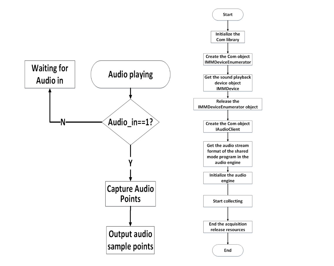
Figure 7. Audio capture software flow diagram
3. The basic principle of socket
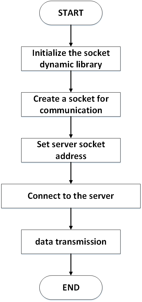
Use the PC as the client and the board as the sever. Connect the DE10NANO development board to the LAN through the network cable. Then use the socket programming to transfer the collected audio data to the DE10NANO development board. Then there is a board to process the data. Take the SOCKET Client as an example, as shown in the left picture.(Figure 8. The socket transfer software flow chart)
4. FFT basic principles
Handle the data collected from the server. Because the data obtained from the collected audio is two-channel, we separate the data of the left and right channels as the real and imaginary parts of the input data of the FFT transform. At the same time, we perform circular conjugate symmetry on the processed data. The circular conjugate antisymmetry divided by the imaginary unit i yields the FFT results of the left and right channels, respectively. Since our sampling rate is 48KHz, we get 48K points in one second, but we can't display every line on our screen (it will cause insufficient resolution between the lines). Therefore, we averaged 1024 points of left and right channels for 8 points. According to the Nyquist sampling theorem, we can find that the frequency range in which distortion does not occur is 0~24 KHz. Therefore, we have the value of each line shape line. All represent the average of 3KHz.
5. Basic principle of image processing
First of all, considering the layout of the interface, we normalize the data obtained by FFT, so that we can ensure that each surface will not be mixed with pixels of other surfaces when displaying; then, the left and right sounds obtained by FFT transformation The data of the track respectively calculate the pixel position and color of the left and right channel spectrum bar graphs; secondly, the cosine component waveforms in the corresponding time domain are generated according to the input spectral components, and the colors are matched with the corresponding frequency spectrum, and finally the drawing is refreshed. , The screen shows the final composite picture. We set the timer to complete the data and image refresh, the ideal refresh rate is 50Hz, but due to the computational delay of the drawing event makes the current refresh efficiency is not high, there is a phenomenon of stall, so can not match the client's data transfer rate . At present, we are still using the server to generate data by FFT transform to generate a display picture. The following is a composite picture and projection display renderings.
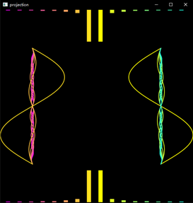

Figure 9. Screen display image and pseudo-holographic projector display
6. The basic principle of holographic display
Based on the principle of Pepper's Ghost phantom imaging, we project the front, back, left and right sides of the image onto our quadra-pyramidal pseudo-holographic projector.
As long as the correct angle is calculated, each screen is an isosceles triangle. The ratio of the waist to the bottom is 1.15:1, which is guaranteed that the diagonals of the top view of the quadrangular pyramid are mutually perpendicular, so that we control the display of the top, bottom, left and right views. The border can be displayed on the holographic projector 360 degree image.
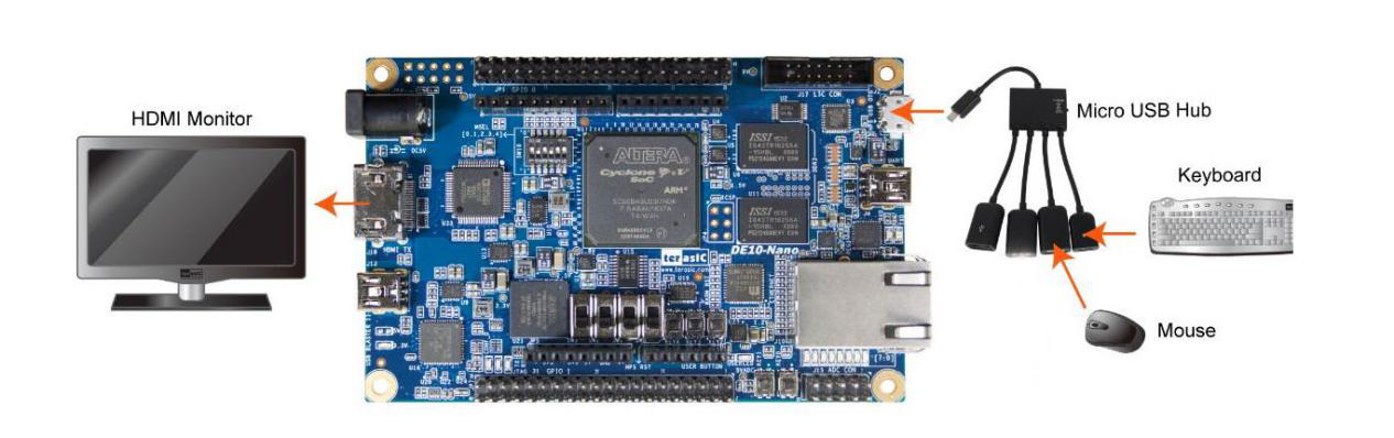
Figure 10. Hardware block diagram of picture display
Performance parameters
1. Audio sampling rate 48000; page refresh rate 1s;
2. The packet loss rate is 129 bytes and 3 are lost, ie 2.3%;
3. At present our system total delay is about 1s
4. Using the Intel FPGA device DE10NANO, its onboard Linux system provides a complete visual operating system that supports multiple processing operations. In addition, the board carries multiple interfaces, such as the HDMI interface, and the application scenario can be expanded for more occasions.
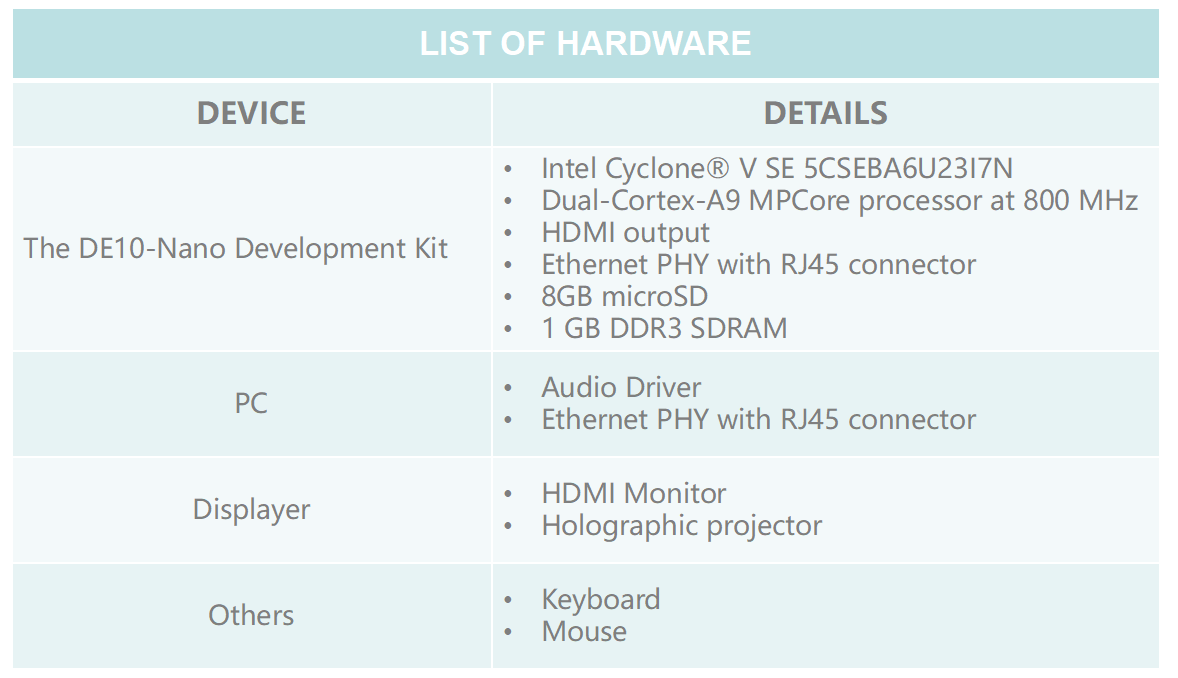
Figure 11. Hardware list table
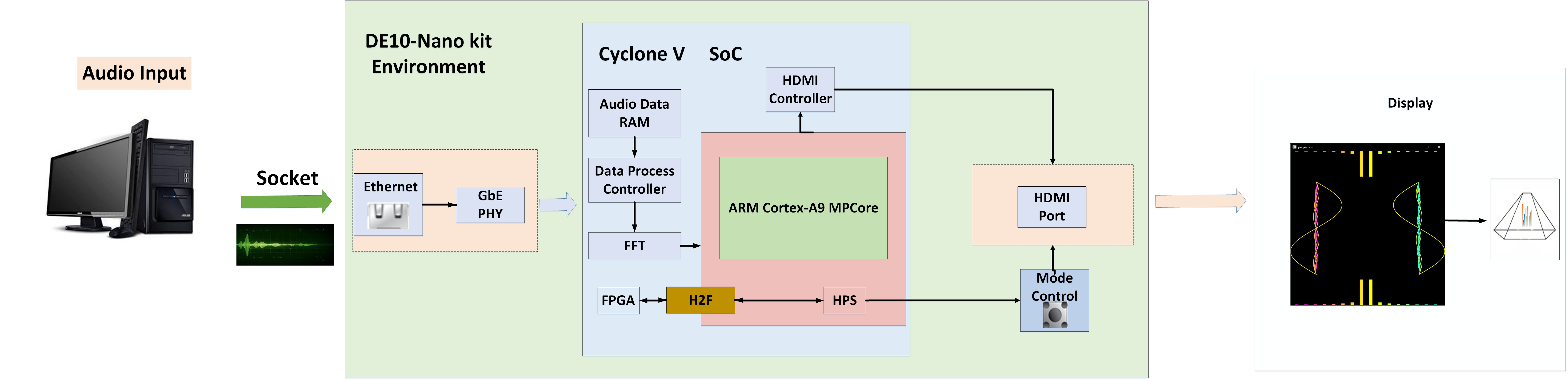
Figure 12. Hardware design block diagram
Thank you very much for your attention to our project! :)